16
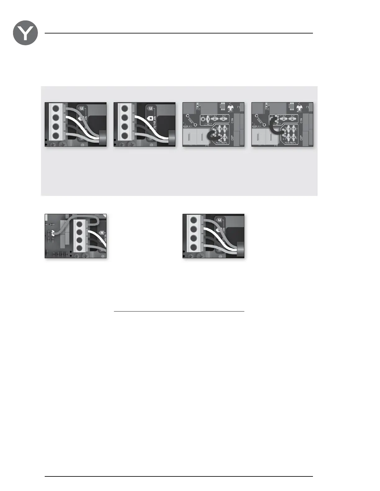
120 V (3 wires) 240 V (4 wires)
DO NOT REMOVE THE BROWN WIRE. Insert each wire
into the appropriate socket of the main entry terminal block
according to the color code indicated on the sticker. Use a
flat screwdriver to tighten the screws on the terminal.
Remove the brown wire and insert each wire into the
appropriate socket of the main entry terminal block accor-
ding to the color code indicated on the sticker. Use a flat
screwdriver to tighten the screws on the terminal.
After making sure wires are securley connected, push them back into the box and replace the cover. Do not over tighten
cover screws (torque to 8 in.lb max {0.9 N.m.}). Connect the bonding conductor to the bonding lug on the side of the spa
pack (a grounded electrode conductor should be used to connect the equipment grounding conductors).
Before November 2014
After November 2014
Electrical wiring
Refer to wiring diagram in the enclosure box lid for more information.
Insert each wire into the appropriate socket of the main
entry terminal block according to the color code indicated
on the sticker. Use a flat screwdriver to tighten the screws
on the terminal.
The heater is factory configured at 240 V (4 kW).
To convert it to 120 V (1 kW) configuration, move the wire
jumper from P35-P20 (240 V) to P35 - P14 (120 V)
240 V (4 wires) 120 V (3 wires) 240 V (4 wires) Default
120 V (3 wires)
Electrical wiring: North Amercian model
 Loading...