www.geeetech.com
Page 26
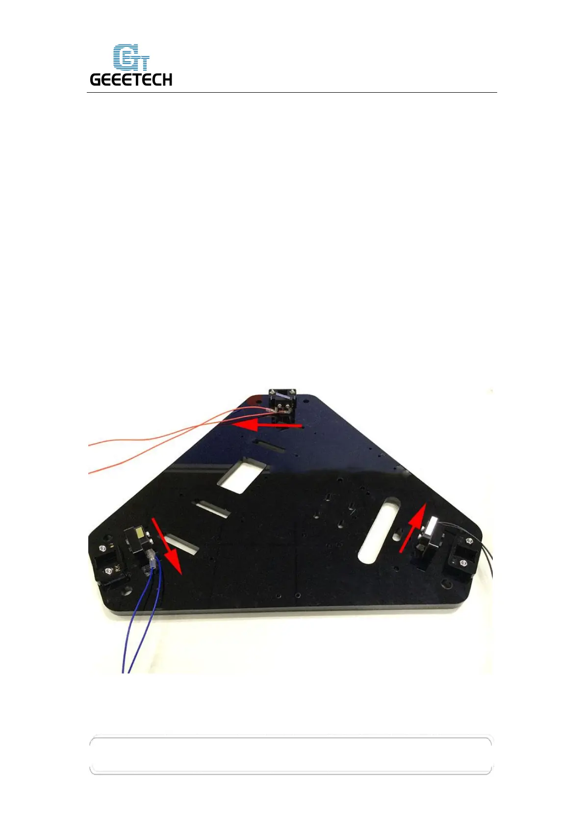
Step 2. Mount the assembled parts onto the top plate (#A1). And attach them
with the M3 x 16 screws (#21), M3 square nuts (#13) and M3 washers (#5).
Again, take note of the endstop mounting direction.
* Note:
1. The opening of all the endstops should either be in the clockwise or anti-clockwise
direction – but they need to be all mounted in the same direction.
2. As we have upgraded the wire of the endstops, now the wire color for the endstop is
fixed now. You can identify the axis by the laser engraving mark on the top plate.
RED X axis
Blue Y axis
Black Z axis
(*Wire color in this picture is not right)
 Loading...