Do you have a question about the Geeetech Prusa I3 Pro C and is the answer not in the manual?
Essential safety guidelines for building and operating the 3D printer, covering electrical and thermal hazards.
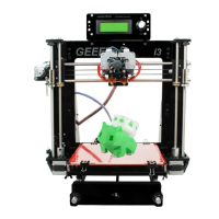
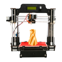
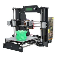
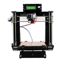
Instructions for unpacking the kit and verifying the condition and presence of all parts.
Attaching the drive pulley to the Y-axis motor shaft securely.
Attaching the Y-axis idler bearing holder to the printer's front support plates.
Mounting the X-axis stepper motor and its associated pulley.
Installing the X-axis end stop switch on the motor end assembly.
Configuring stepper motor driver jumper caps for appropriate microstepping.
Connecting X, Y, and Z axis stepper motor wires to the control board.
Connecting wires for heatbed and extruder heating elements.
Connecting thermistor wires for temperature sensing.
Connecting end stop sensor wires for axis homing.
Connecting cooling fan wires to the control board.
Connecting the LCD encoder and SD card reader cables.
Connecting the main power input to the control board.
| Build Volume | 200 x 200 x 180 mm |
|---|---|
| Layer Resolution | 0.1 - 0.3 mm |
| Nozzle Diameter | 0.4 mm |
| Filament Diameter | 1.75 mm |
| Heated Bed | Yes |
| Bed Temperature | up to 100 °C |
| Nozzle Temperature | up to 250 °C |
| Connectivity | USB, SD Card |
| Machine Weight | 8 kg |
| Print Technology | FDM (Fused Deposition Modeling) |
| Supported Filament | PLA, ABS, PETG |
| Power Supply | 12V |