www.geeetech.com
Page 52
Step 1. Place the print head assembly on to the building platform.
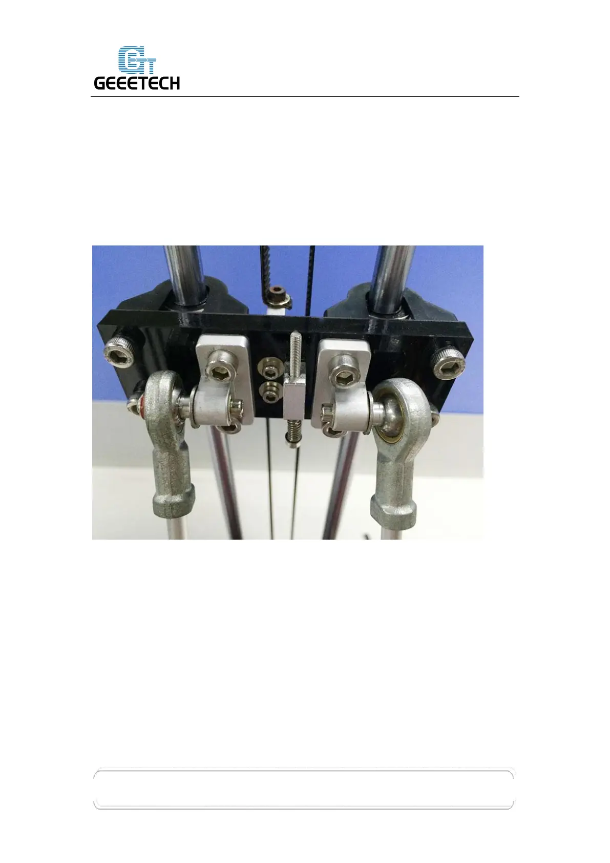
Step 2. Working with the “X” axis first, slide the diagonal rod (#4) on to the on the
rod-end bearing holder located on the assembled print assembly, fixing it
on with a round head screw with pad (#16).
Step 3. Fix the other end of the diagonal rod (#4) to the carriage located on the “X
axis” tower with a round head screw with pad (#16).
 Loading...