ADV200 • Functions description and parameters list 101
Menu PAR Description UM Type FB BIT Def Min Max Acc Mod
21.5 2408Vffrequency Hz FLOAT CALCF 10.0 2000.0
ERWZS
V
Setting of the motor rated frequency (indicated on the motor data plate)
This is the frequency at which the drive output voltage reaches the maximum output voltage (Vfvoltage) on
the motor.
Menu PAR Description UM Type FB BIT Def Min Max Acc Mod
21.6 2410Vfvoltage1 V FLOAT CALCF CALCF CALCF
ERWZS
V
Setting of an intermediate voltage value for the custom V/f characteristic curve.
Menu PAR Description UM Type FB BIT Def Min Max Acc Mod
21.7 2412Vffrequency1 Hz FLOAT CALCF 0.0 CALCF
ERWZS
V
Setting of an intermediate frequency value for the custom V/f characteristic curve.
Menu PAR Description UM Type FB BIT Def Min Max Acc Mod
21.8 2414Vfvoltage0 V FLOAT CALCF 0.0 CALCF ERWZS V
Compensation of IR voltage drop at 0 Hz. This parameter must be increased in case of pure V/f control. The in-
crease depends on the size of the motor. Values that are too high could cause an overcurrent and motor saturation.
Menu PAR Description UM Type FB BIT Def Min Max Acc Mod
21.9 2430Vfshape ENUM Linear 0 2 ERWS V
Selection of the type of V/f characteristic curve
0 Linear
1 Custom
2 Quadratic
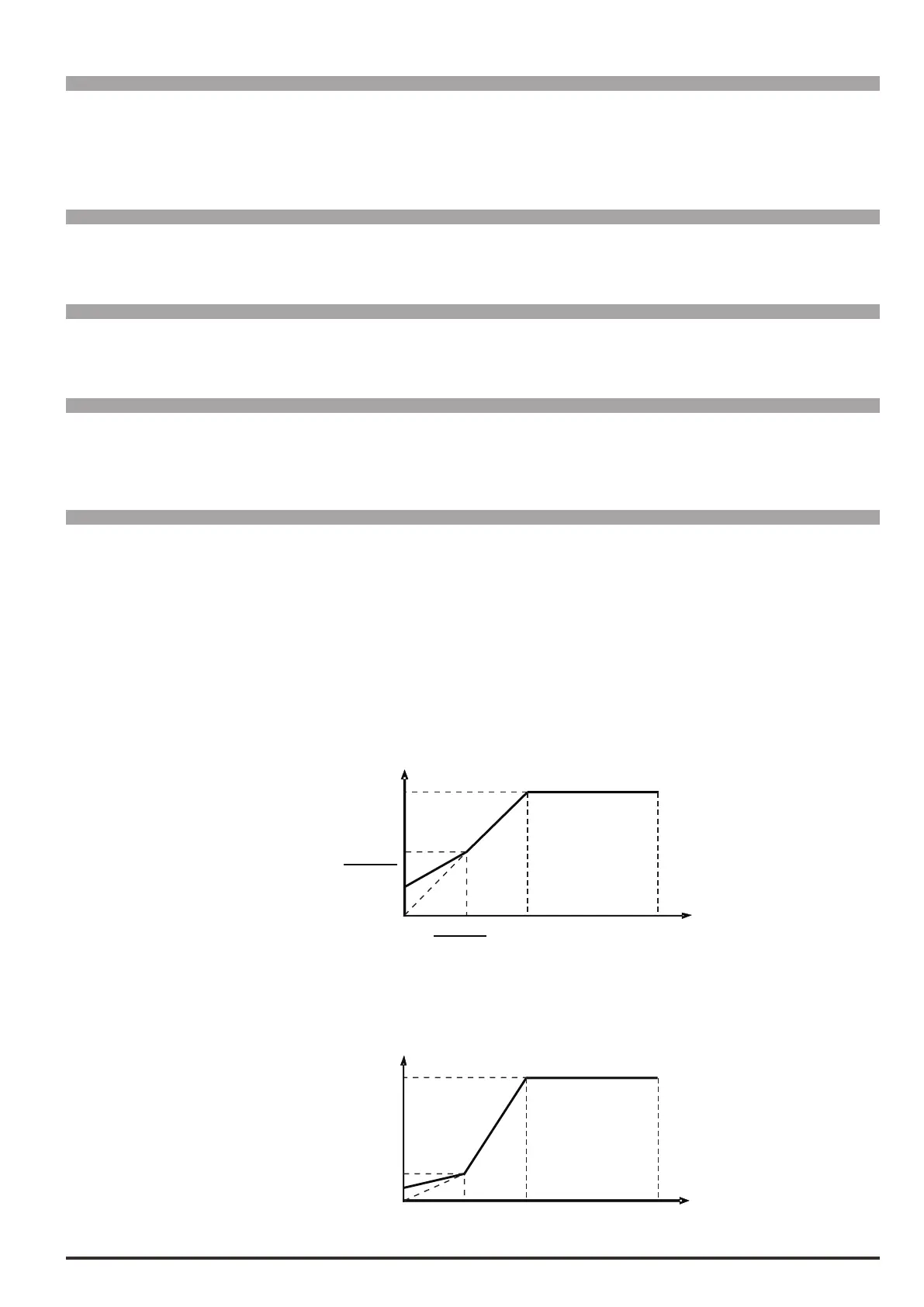
Set 0 (Linear) to obtain a linear V/f characteristic curve, on which the intermediate points are reset to a value
that is equal to half those of parameters 2406 and 2408.
The Boost joins the curve automatically.
Par.2412
2
2
Par.2406
Par.2408
Par.2410
Par.2400
V
Hz
Set 1 (Custom) to obtain a customized V/f characteristic curve, in which the intermediate voltage and frequen-
cy values are dened by parameters 2410 and 2412, as is the point at which the Boost joins the characteristic
curve.
Par.2406
Par.2408
Par.2410
Par.2400
Par.2412 Hz
V

 Loading...


