62 ADV200 • Functions description and parameters list
14–ANALOGINPUTS
Menu PAR Description UM Type FB BIT Def Min Max Acc Mod
14.1 1500Analoginput1mon cnt INT16 16/32 0 0 0 R FVS
14.17 1550Analoginput2mon cnt INT16 16/32 0 0 0 R FVS
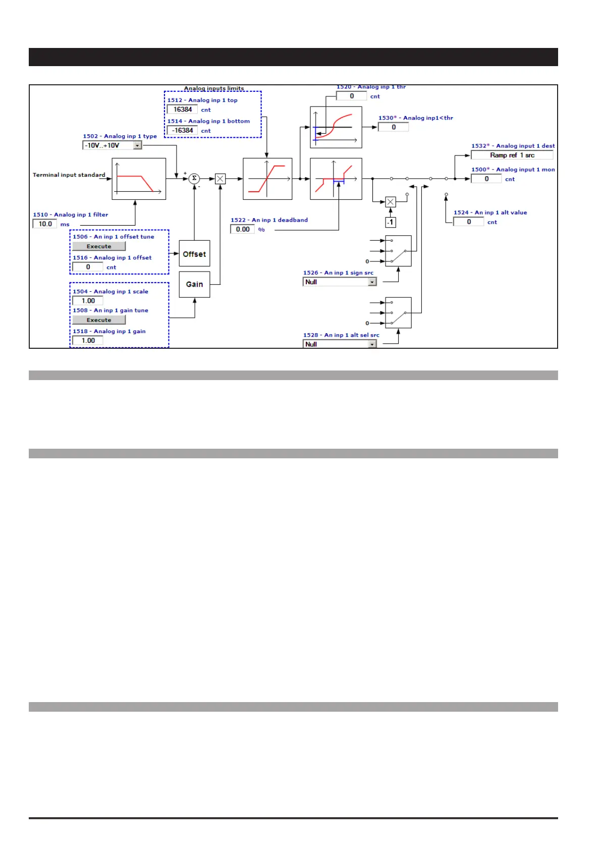
The value of the voltage on the output of the function block of the relative analog input is displayed.
Menu PAR Description UM Type FB BIT Def Min Max Acc Mod
14.2 1502Analoginp1type ENUM -10V..+10V 0 2 RW FVS
14.18 1552Analoginp2type ENUM -10V..+10V 0 2 RW FVS
Selection of the type of input (voltage or current). Depending on the input signal, move the switches on the
regulation card. The factory parameter is inputs set for differential voltage signals (± 10V).
0 -10V…+10V
1 0,20mA … 10V
2 4..20mA
Select option 0 in order to connect a maximum voltage of ±12.5V (typically ±10V/5mA) to the analog input con-
cerned. If the signal is used as a reference, reverse the direction of rotation by inverting the voltage polarity.
Select option 1 to connect a max voltage of 12.5V (typically 10V/5mA) or a signal in current from 0 ... 20 mA to
the analog input concerned. The signal must be positive.
Select option 2 to connect a current signal of 4...20 mA to the analog input concerned. The signal must be posi-
tive.
Menu PAR Description UM Type FB BIT Def Min Max Acc Mod
14.3 1504Analoginp1scale FLOAT 1.0 -10.0 10.0 RW FVS
14.19 1554Analoginp2scale FLOAT 1.0 -10.0 10.0 RW FVS
Setting of a multiplier factor to apply to the relative analog input.

 Loading...


