ADV200 • Functions description and parameters list 85
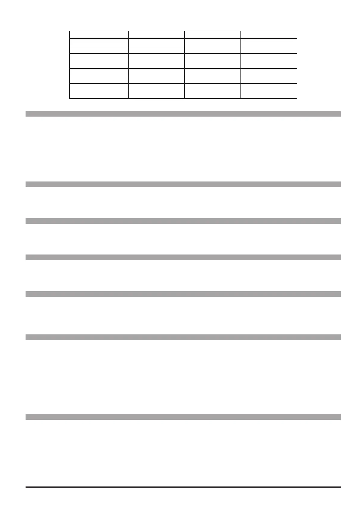
Encoder option type Def Min Max
Enc 1 Digital F Digital FP Digital F
Enc 2 Sinus Sinus Sinus
Enc 3 Sinus SINCOS Sinus SINCOS Sinus SINCOS
Enc 4 Sinus SSI Sinus ENDAT Sinus SSI
Enc 5 Sinus HIPER Sinus HIPER Sinus HIPER
Enc 6 Resolver Resolver Resolver
Enc 7 Digital F Digital FP Digital F
Enc 8 SINCOS / No inc dig SINCOS / No inc dig SINCOS / No inc dig
Menu PAR Description UM Type FB BIT Def Min Max Acc Mod
17.19 2134Encoder1speedfilter ms FLOAT 2.0 0.1 20.0 ERW FVS
Setting of the time constant of the lter applied to the feedback encoder pulse reading. The parameter affects
both the accuracy of the speed measurement and the dynamics obtainable in closed loop control. Long updat-
ing times allow greater stability (more ltering) of the speed measurement, as a higher number of encoder
pulses are counted at a given speed of rotation. On the other hand, the use of a speed measurement lter
introduces delays that do not permit high control loop dynamics. Low settings extend the regulation bandwidth
but may accentuate any disturbance.
Menu PAR Description UM Type FB BIT Def Min Max Acc Mod
17.20 2150Encoder1speed rpm INT16 16/32 0 0 0 ER FVS
The motor speed measured by the encoder is displayed.
Menu PAR Description UM Type FB BIT Def Min Max Acc Mod
17.21 2162Encoder1position cnt UINT16 16 0 0 0 ER FVS
The encoder position is displayed. The scale is Number of encoder impulses *4.
Menu PAR Description UM Type FB BIT Def Min Max Acc Mod
17.22 5100Encoder2pulses ppr UINT16 CALCI CALCI CALCI ERWZ FVS
Setting of the number of impulses/rev of the incremental encoder mounted in slot 1 or 3.
Menu PAR Description UM Type FB BIT Def Min Max Acc Mod
17.23 5102Encoder2supply V FLOAT 5.2 5.2 CALCF ERWZ FVS
Setting of the encoder supply voltage supplied by the relative optional card. Min and max values refer to the
incremental digital encoder cards with one or two encoders.
Menu PAR Description UM Type FB BIT Def Min Max Acc Mod
17.24 5104Encoder2inputcfg ENUM TTL 0 1 ERWZ FVS
Setting of the input conguration of the incremental digital encoder, TTL or HTL.
0 HTL
1 TTL
The value of this parameter is automatically set in HTL when the value entered in the Encoder2supply pa-
rameter is more than 6.0V.
Menu PAR Description UM Type FB BIT Def Min Max Acc Mod
17.25 5106Encoder2repetition ENUM
No division
0 3 ERWZ FVS
Setting of the divider to apply to the encoder repetition output frequency.
0 No division
1 Divide 2
2 Divide 4
3 Divide 8

 Loading...


