Unpacking and Inspection
Installation Guidelines For 60 Hz EcoGen™ Generators 9
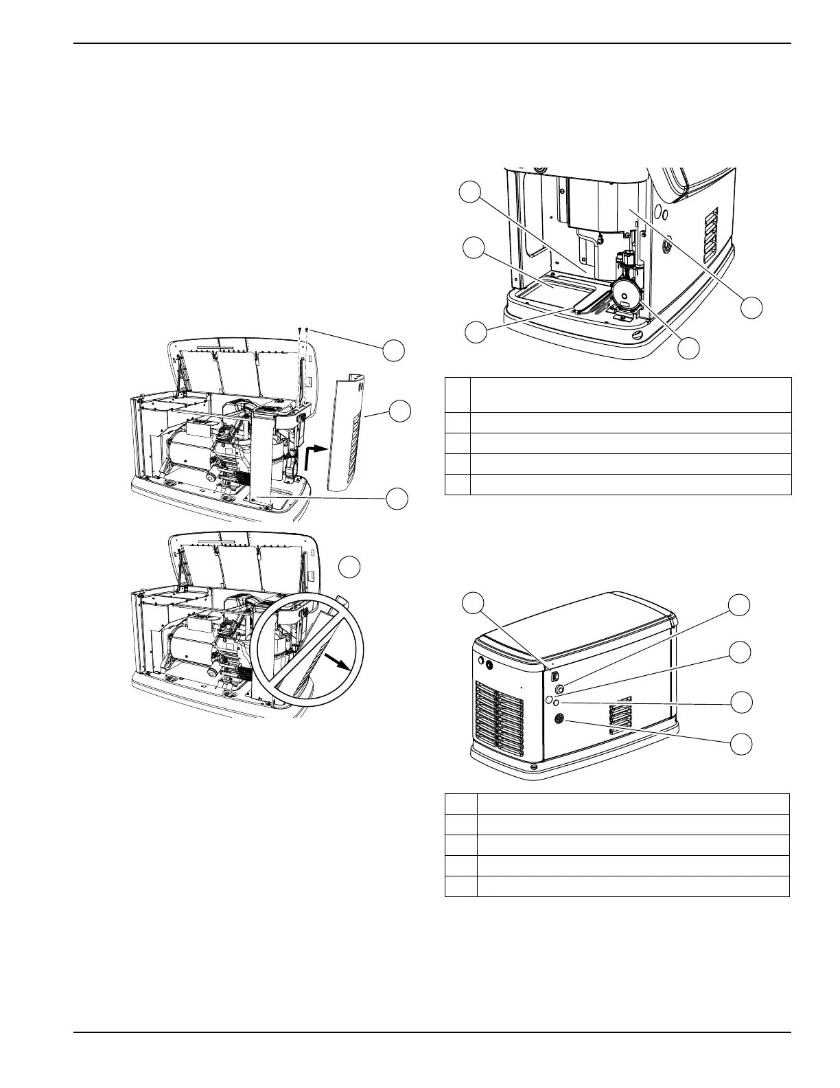
Intake Side Panel Removal
See Figure 2-6. The intake side panel (A) must be
removed to access battery compartment, fuel regulator,
and sediment trap.
1. Raise lid and remove front panel.
2. Use a hex key to remove two mounting screws (B)
and the hex screw on the L-bracket.
3. Lift intake panel up and away from generator.
4. Inspect for any hidden freight damage. Contact
freight carrier if damage is present.
NOTE: Always lift intake side panel straight up before
pulling away from enclosure. Do not pull panel away from
enclosure before lifting up (D).
Figure 2-6. Intake Side Panel Removal
Customer Connections and Loose
Parts
See Figure 2-7 and Figure 2-8 for customer connections
and loose parts location. Figure 2-10 illustrates parts
shipped loose.
Figure 2-7. Customer Connection Area and Loose
Parts Location
Rear Connections
Figure 2-8. Rear Connections
NOTE: The generator is equipped with a Wi-Fi module.
See Wi-Fi module owner’s manual for further instruction.
A Customer electrical connection area (behind access
panel)
B Fuel regulator with sediment trap
C Battery compartment (battery not supplied)
D Positive (+) and negative (-) battery cables
E Location of “Loose Shipped Parts”
A Wi-Fi module
B Main AC/Control wiring hole for 1-1/4 in conduit
C Main AC/Control wiring hole for 3/4 in conduit
D Fuel connection hole
E Auxiliary shutdown switch
 Loading...