Electrical Connections
30 Installation Guidelines For 60 Hz EcoGen™ Generators
Control Wiring
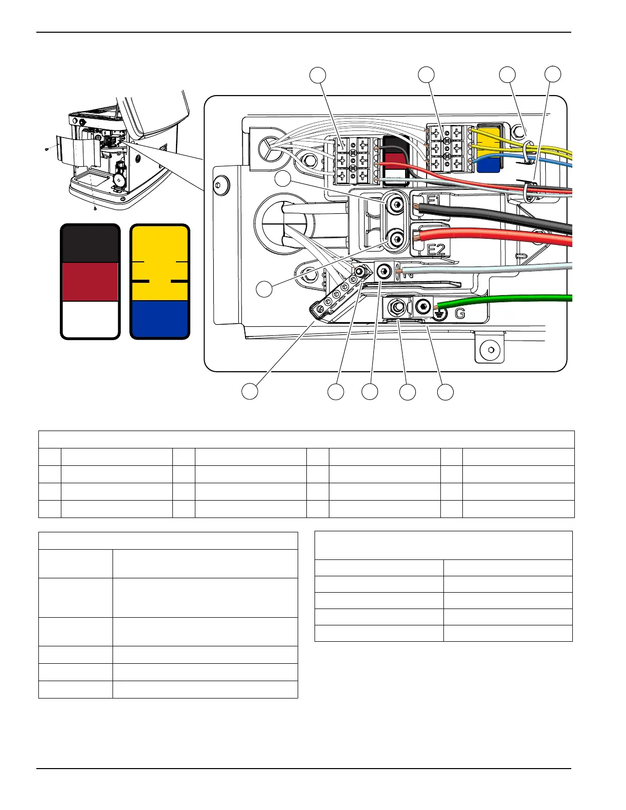
Figure 6-1. Electrical Wiring Connections
* Must be connected to keep battery charged whether unit is running or not.
** Required if generator is paired with optional Digital Power Management (DPM) smart technology.
*** No connection required in off-grid mode.
1
1
2
2
VAC LOAD
SUPPLY
3
3
UTILITY
SENSE
N1
N2
T1
DC
GROUND
1
1
2
2
TRANSFER
3
3
+ 12 VDC
0
194
23
1
1
2
2
VAC LOAD
SUPPLY
3
3
UTILITY
SENSE
N1
N2
T1
DC
GROUND
1
1
2
2
TRANSFER
3
3
+ 12 VDC
0
194
23
Table 6-1. Electrical Wiring Connection Points
ID Description ID Description ID Description ID Description
A Control wire terminal block C2 Wire tie for control wires E2 Power lug E2 H Neutral stud
B Sense wire terminal block D Neutral lug F Ground stud J Neutral bar
C1 Wire tie for sense wires E1 Power lug E1 G Ground lug — —
Table 6-2. Customer Wiring Connections
Terminal Number-
ing Decal
Wire Numbers
YELLOW ***
N1 & N2 - 240 VAC - Sensing for utility dropout
and pickup. Required for battery heater and oil
heater.
BLUE *
T1 - Fused 120 VAC for battery charger.
Breather heater requires T1 connection to 120V.
BLACK ** 0 - DC (-) Common ground wire
RED *** 194 - DC (+) 12 VDC for transfer controls
WHITE *** 23 - Transfer control signal wire
Table 6-3. Control Wire Recommended Length and Size
(Copper Conductors Only)
Maximum Wire Length Recommended Wire Size
1–115 ft (0.3–35 m) No. 18 AWG
115–185 ft (35–56 m) No. 16 AWG
185–295 ft (56–89 m) No. 14 AWG
295–460 ft (89–140 m) No. 12 AWG