Generator Placement
Installation Guidelines For 60 Hz EcoGen™ Generators 19
Section 4: Generator Placement
Generator Placement
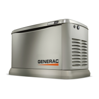
See Figure 4-1. All air-cooled generators come with a
composite pad. The composite pad elevates the genera-
tor and helps prevent water from pooling around base.
Figure 4-1. Composite Pad
The composite pad allows the generator to be placed on
two types of surfaces:
• on 5 in (127 mm) of compacted pea gravel or
crushed stone
• on a concrete pad
See local codes to verify what type of site base is
required. If a concrete pad is required, all federal, state,
and local codes must be followed. Place generator, with
composite pad attached, and position correctly as per
dimensional information given in Site Selection and
Preparation.
NOTE: Generator must be level within 0.5 in (13 mm).
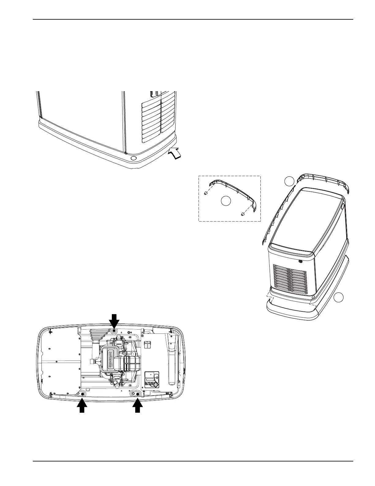
NOTE: See Figure 4-2. DO NOT remove composite pad
for mounting generator to concrete. The composite pad is
pre-drilled to accommodate mounting bolts.
Figure 4-2. Mounting Hole Locations
Three mounting holes are available if codes require
securing generator to concrete. Mounting holes are
located inside the generator compartment—two in front
and one in back.
Three 3/8 in (or M10) lag bolts (not supplied) are recom-
mended for securing the generator to a concrete pad.
NOTE: The top of the generator carton has a template
which can be used to mark the concrete pad to pre-drill
the mounting holes.
Fascia Installation (If Applicable)
1. Locate the four threaded black rubber bumpers
supplied with the loose parts. (See Parts Shipped
Loose.)
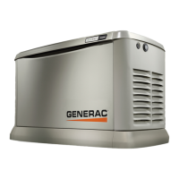
2. See Figure 4-3. Remove bumpers from bag and
screw into threaded holes located inside the end
pieces of the fascia (two each) opposite one
another (A).
Figure 4-3. Fascia Installation
3. Snap one of the end pieces into one of the front/
rear pieces of fascia. Repeat this action with the
other two remaining pieces of fascia (B).
NOTE: Do not assemble all four pieces together at this
point.
4. Place both assemblies at the generator base and
fit the rubber mounts into the lifting holes in the
generator base (C).
5. Once aligned, snap together the two remaining
connection points.