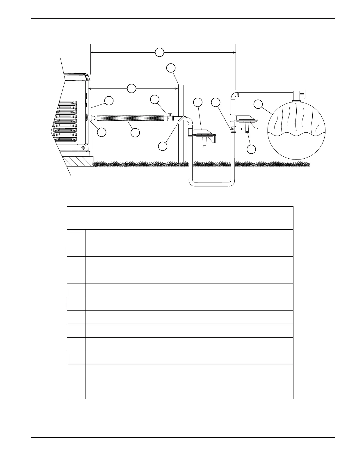
Figure 5-7. LP Vapor Installation (typical)
LP BTU = ft
3
/h X 2500
Megajoules = m
3
/h X 93.15
A BTU and pressure decal
B Minimum distance from rear obstruction—see Site Selection
C Manual shutoff valve (pressure port optional)
D Pipe nipple (field supplied)
E Flexible fuel line
F Check distance with gas provider
G Reinforcing rod
H Clamp
J Secondary fuel pressure regulator
K Manual shutoff valve
L Primary fuel pressure regulator
M Fuel tank—sized large enough to provide required BTUs for generator and
ALL connected appliance loads. Be sure to correct for weather evaporation.
LP BTU = ft
3
/h X 2500
Megajoules = m
3
/h X 93.15
A BTU and pressure decal
B Minimum distance from rear obstruction
C Manual shutoff valve (pressure port optional)
D Pipe nipple (field supplied)
E Flexible fuel line
F Check distance with gas provider. See Site Selection .
G Reinforcing rod
H Clamp
J Secondary fuel pressure regulator
K Manual shutoff valve
L Primary fuel pressure regulator
M Fuel tank—sized large enough to provide required BTUs for generator and
ALL connected appliance loads. Be sure to correct for weather evaporation.
001809
H
C
A
D
E
B
G
F
KJ
L
M
 Loading...