Electrical Connections
Installation Guidelines For 60 Hz EcoGen™ Generators 27
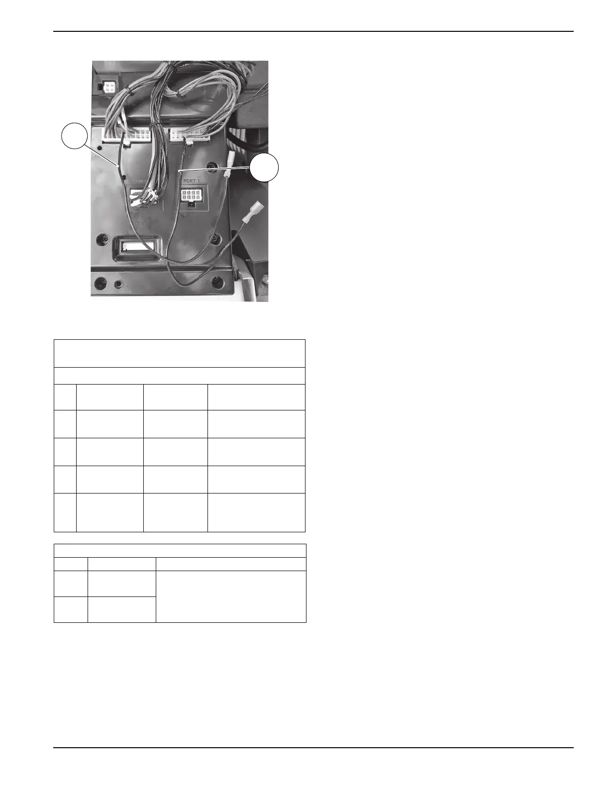
Figure 6-2. Two-Wire Start Connections
Main AC Wiring
NOTE: Main AC wiring must be in accordance with local
jurisdiction and codes.
NOTE: The generator lugs are rated at 167 °F (75 °C),
copper or aluminum.
1. Strip the insulation off the wire ends. Do not remove
excessive insulation.
2. See Figure 6-1. Loosen the lugs at neutral (D),
ground (G), and power wire (mains) terminals (E1,
E2).
3. Connect the ground wire to the ground lug and torque
to the required specification. See Table 6-4.
4. Connect the neutral wire to the neutral lug if
applicable. Torque to the required specification. See
Table 6-4.
5. Insert the power wires (E1 and E2) into their
corresponding lugs. Torque to the proper specification.
6. Verify the factory-installed ground and neutral
connections are properly tightened to 25 in-lb (2.82
Nm).
NOTE: The neutral wire must remain connected to keep
the battery charged whether the generator is running or
not.
NOTE: Neutral bonding – For installations that require
the neutral to be bonded to the ground, this is done on
the customer connections terminals inside the generator.
See Figure 6-1. Connect a suitably sized wire from the
neutral bar (J) to the ground stud (F). Torque the nut on
the ground stud to 35 in-lbs (3.95 Nm). This is normally
required when the generator is the source in a separately
derived system. The installation must be made in
accordance with NEC Articles 250.30 and 250.35(A) if
the generator will be installed as a separately derived
system.
NOTE: Torque all wiring lugs, bus bars, and connection
points to the proper torque specifications.
Conductors of AC and DC circuits, rated 1000 volts
nominal or less, shall be permitted to occupy the same
equipment, cable, or conduit. All conductors shall have
an insulation rating equal to at least the maximum circuit
voltage applied to any conductor within the equipment,
cable, or conduit. See NEC 300.3(C)(1).
Service Entrance Decals
See Figure 2-6. Locate the service entrance-related
decals in the loose parts bag.
• Place the service disconnect decal next to the Main
Line Circuit Breaker (Generator Disconnect).
• Place the service entrance warning decal in an
appropriate location according to the instructions
printed on the decal.
Table 6-4. Ground and Neutral Connections
(Copper or Aluminum Conductors)
Refer to national and/or local codes to verify correct wire sizes.
No. Description
Recommended
Wire Size
Torque Spec
1
Power wire
terminals
2/0 to 8 AWG 120 in-lb (13.56 Nm)
2
Large neutral
lug
2/0 to 14 AWG 120 in-lb (13.56 Nm)
3
Large ground
lug
2/0 to 14 AWG 120 in-lb (13.56 Nm)
4 Neutral bus bar
4-6 AWG
8 AWG
10-14 AWG
35 in-lb (3.95 Nm)
25 in-lb (2.82 Nm)
20 in-lb (2.26 Nm)
Table 6-5: Remote Start Connections
Wire Connection
Location
178
Female Faston
Two-Wire Start
Hanging from controller above battery
compartment
183
Female Faston
Two-Wire Start
 Loading...