Electrical Connections
26 Installation Guidelines For 60 Hz EcoGen™ Generators
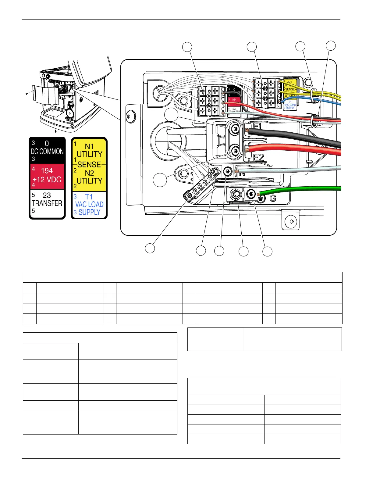
Control Wiring
Figure 6-1. l Electrical Wiring Connections
* Must be connected to keep battery charged whether unit is running or
not.
** Required if generator is paired with Generac Smart Power manage-
ment transfer switch.
Table 6-1. Electrical Wiring Connection Points
ID Description ID Description ID Description ID Description
A Control wire terminal block C2 Wire tie for sense wires E2 Power lug E2 H Neutral stud
B Sense wire terminal block D Neutral lug F Ground stud J Neutral bar
C1 Wire tie for control wires E1 Power lug E1 G Ground lug — —
Table 6-2. Customer Wiring Connections
Terminal Numbering
Decal
Wire Numbers
YELLOW
NO. 1 & NO. 2
N1 & N2 - 240 VAC - 240 VAC for Cold
Weather Kit (if required) from a dedicated 2
Pole 15A Breaker
BLUE NO. 3 *
T1 - Fused 120 VAC for battery charger
from a 1 Pole 15A Breaker
BLACK NO.3 ** 0 - DC (-) Common ground wire
RED NO. 4
194 - DC (+) 12 VDC for transfer controls -
NO CONNECTION REQUIRED FOR
ECOGEN UNITS
WHITE NO. 5
23 - Transfer control signal wire- NO
CONNECTION REQUIRED FOR ECOGEN
UNITS
Table 6-3. Control Wire Recommended Length and Size
(Copper conductors only)
Maximum Wire Length Recommended Wire Size
1–115 ft (1–35 m) No. 18 AWG
115–185 ft (35–56 m) No. 16 AWG
185–295 ft (56–89 m) No. 14 AWG
295–460 ft (89–140 m) No. 12 AWG