Section 2 Engine DC Control System
8 Diagnostic Repair Manual
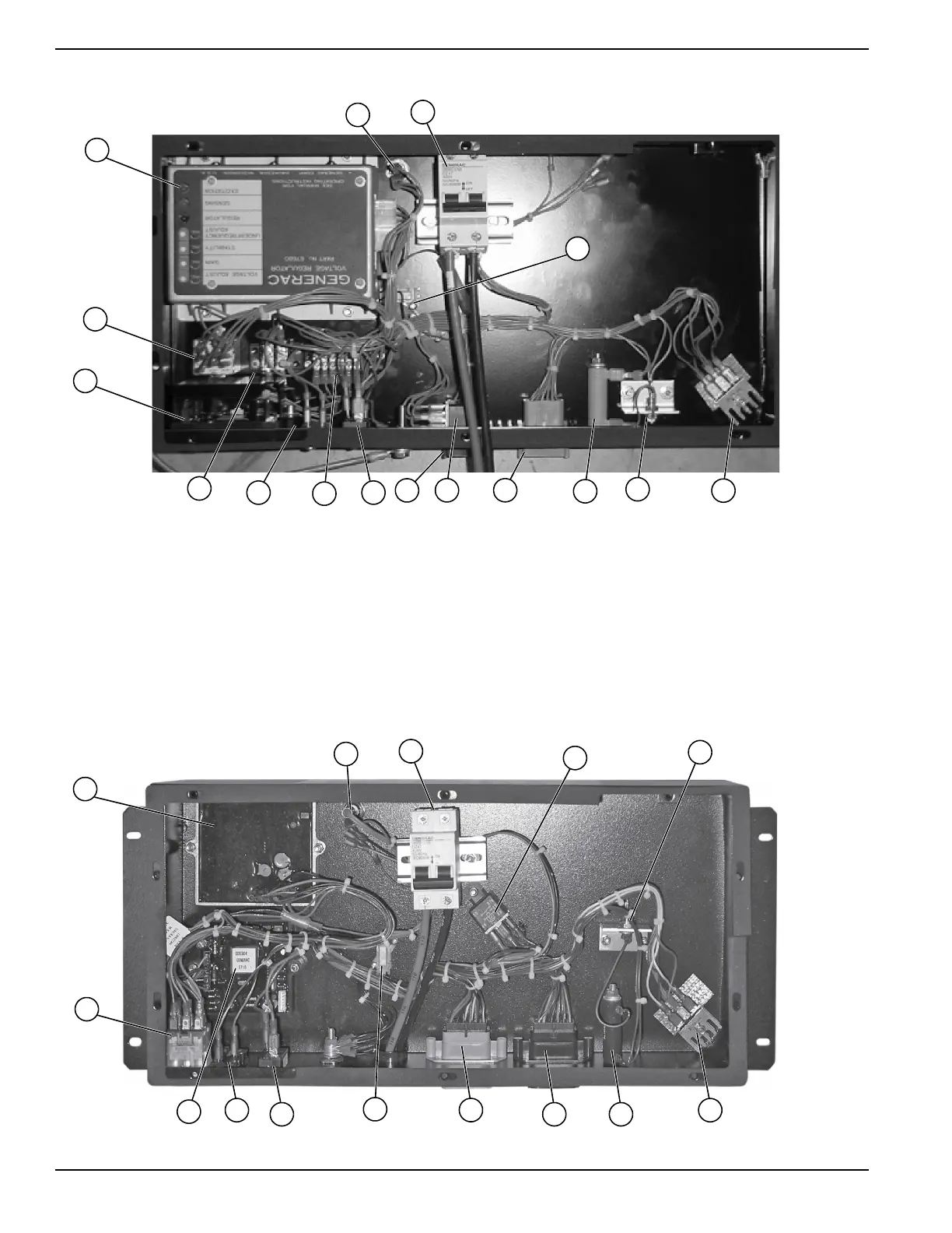
Control Panel Component Identification
Figure 2-2. Control Panel Component Identification (Older Units)
Figure 2-3. Control Panel Component Identification (Newer Units)
A. Voltage Regulator
B. 10 Amp Fuse (F1)
C. 50 Amp Circuit Breaker
D. Start Stop Relay (SSR)
E. Printed Circuit Board
F. Terminal Board (TB2)
G. Excitation Circuit Breaker (CB2)
H. Terminal Board (TB2)
I. 10 Amp Auto Reset Breaker (CB1)
J. Connector (C2)
K. Starter Contactor Relay (SCR)
L. Connector (C1)
M. Resistor (R1)
N. Diode (D1)
O. Battery Charge Rectifiers (BCR1 & BCR2)
P. Idle Control Transformers (ICT)

 Loading...