Section 1 Description and Components
2 Diagnostic Repair Manual
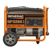
Figure 1-2. Stator Assembly Leads
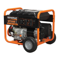
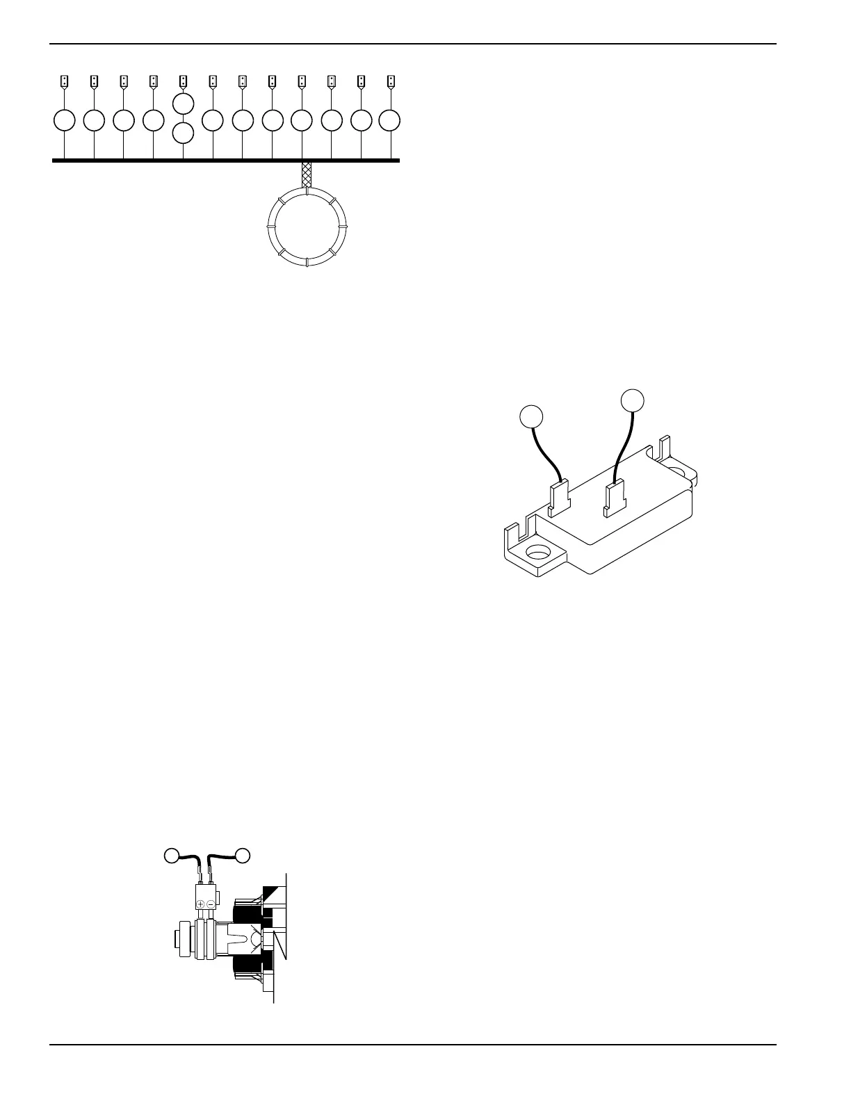
Brush Holder and Brushes
The brush holder is retained to the rear bearing carrier
with two self-tapping screws. A positive (+) and a
negative (-) brush are retained in the brush holder, with
the positive (+) brush riding on the slip ring nearest the
rotor bearing.
See Figure 1-3. Wire 4 connects to the positive (+) brush
and wire 0 to the negative (-) brush. Wire 0 connects to
frame ground. Rectified and regulated excitation current,
as well as current from a field boost circuit, are delivered
to the rotor windings via wire 4, and the positive (+) brush
and slip ring. The excitation and field boost current
passes through the windings and to frame ground via the
negative (-) slip ring and brush, and wire 0. This current
flow creates a magnetic field around the rotor having a
flux concentration that is proportional to the amount of
current flow.
Figure 1-3. Brush Holder and Brushes
Other AC Generator Components
Some AC generator components are housed in the
generator control panel enclosure. These are the
excitation circuit breaker, the voltage regulator, and the
main line circuit breaker.
Excitation Circuit Breaker
See Figure 1-4. The excitation circuit breaker (CB2) is
housed in the generator control panel enclosure and
electrically connected in series with the excitation (DPE)
winding output to the voltage regulator. The breaker is
self-resetting, therefore its contacts will close again when
excitation current drops to a safe value.
If the circuit breaker has failed open, excitation current
flow to the voltage regulator and rotor windings will be
lost. Without excitation current flow, AC voltage induced
into the stator AC power windings will drop to a value in
proportion with the rotor residual magnetism.
Figure 1-4. Excitation Circuit Breaker
Voltage Regulator
A typical Voltage Regulator is shown in Figure 1-5 (12.5
kW & Older 15 kW Units) or Figure 1-6 (Newer 15 kW
and all 17.5 kW Units). See Figure 1-4. Unregulated AC
output from the stator excitation winding is delivered to
the regulator’s DPE terminals, via wire 2, the excitation
circuit breaker and wire 162, and wire 6. The voltage
regulator rectifies the current and based on stator AC
power winding sensing, regulates it. The rectified and
regulated excitation current is then delivered to the rotor
windings from the positive (+) and negative (-) regulator
terminals, via wire 4 and wire 0. Stator AC power winding
sensing is delivered to the regulator “SEN” terminals via
wires 11S and 44S, or 11S and 22S, depending on the
model.
The regulator provides over-voltage protection, but does
not protect against under-voltage. On occurrence of an
over-voltage condition, the regulator will shut down and
complete loss of excitation current to the rotor will occur.
Without excitation current, the generator AC output
voltage will drop to approximately one-half (or lower) of
the unit’s rated voltage.
Item Wire Number Winding
A 11 Power Winding
B 44 Power Winding
C 22 Power Winding
D 11S Sense Lead Power
E 44S Sense Lead Power (Older Style)
F 22S Sense Lead Power (Newer Style)
G 55A Battery Charge
H 66A Battery Charge
I 77A Battery Charge
J 2 Excitation
K 6 Excitation
L 55 10 Amp Battery Charge
M 66 10 Amp Battery Charge
N 77 10 Amp Battery Charge
A
B C D
E
F
G H I J K L M
004714

 Loading...