Section 4 AC Diagnostic Tests
40 Diagnostic Repair Manual
Results
If Continuity was not measured across each wire, repair
or replace the wires as needed. If Continuity was
measured refer back to flow chart.
Test 7 – Check Field Boost
Procedure
1. Set DMM to measure DC voltage.
2. Disconnect the six pin connector from the voltage
regulator.
3. Disconnect connector C1. See Control Panel
Component Identification for connector location.
4.
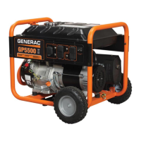
See
Figure 4-14
. Disconnect wire 16 from the
starter contactor relay (SCR). This will prevent the
unit from cranking when placed in the START
position.
Figure 4-14. Starter Contactor Relay
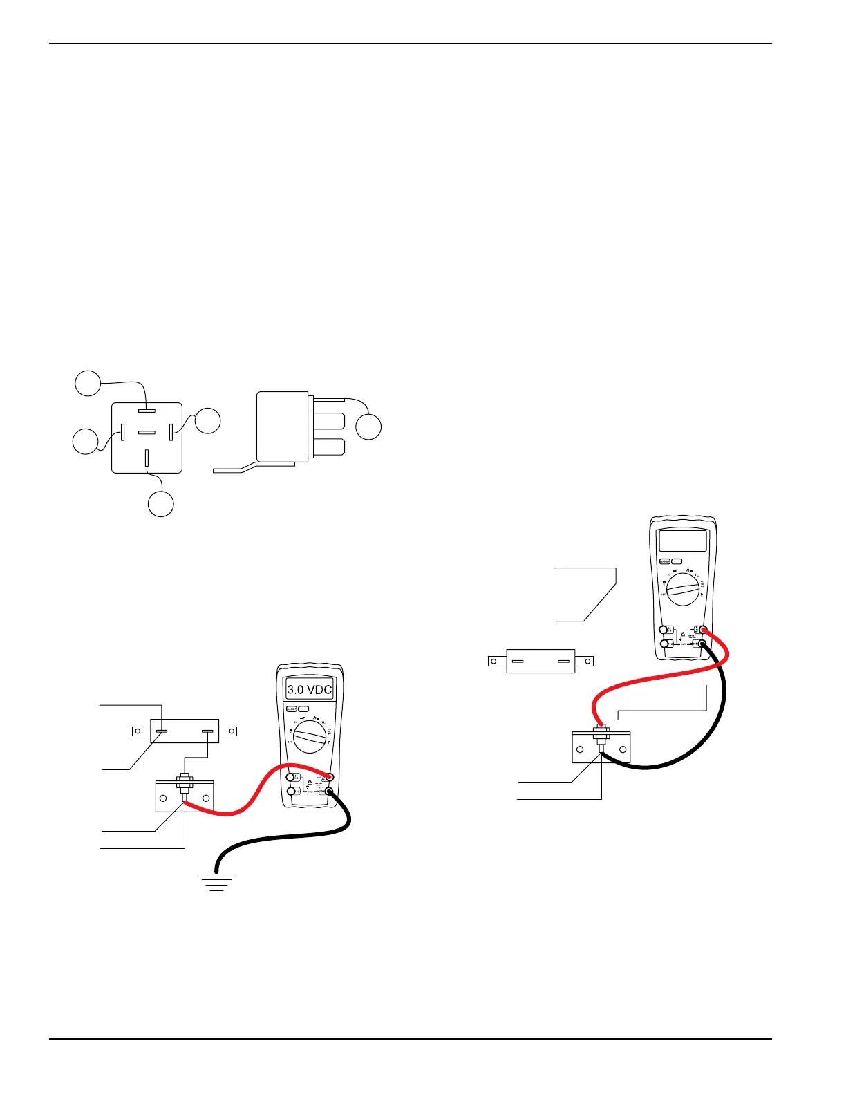
5. See Figure 4-15.
a. Connect the positive meter test lead to wire 4 at
diode D1. Wire 4 is soldered to the diode.
b. Connect the negative meter test lead to the
ground terminal.
Figure 4-15. Testing Field Boost
6. Set the start-run-stop switch (SW1) to START and
measure the DC voltage.
a. Approximately 12 VDC should be measured.
7. Connect the six pin connector to the voltage
regulator.
8. Connect the C1 connector.
9. Connect wire 16 to the starter contactor relay.
Results
1. If 12 VDC was measured in step 6 the field boost
circuit is working. Refer back to the flow chart.
2. If field boost voltage was not measured refer back
to the flow chart.
Test 8 – Diode/Resistor
Procedure
1. Set DMM to the diode test range.
2. Disconnect the six pin connector from the voltage
regulator.
3. Disconnect connector C1. See Control Panel
Component Identification for connector location.
4. Disconnect both wires from resistor R1.
5. See Figure 4-16.
a. Connect the positive meter test lead to the top
terminal of diode D1.
a. Connect the negative meter test lead to the
bottom of the diode.
a. Infinity or “Open” should be measured.
Figure 4-16. Diode Test Step 5
6. See Figure 4-17.
a. Connect the positive meter test lead to the
bottom terminal of diode D1.
b. Connect the negative meter test lead to the top
of the diode.
c. Approximately 0.5 volts should be measured.
7. Set DMM to measure resistance.
a. Connect one meter test lead to the top terminal
of diode D1.
D2
4
14
WIRE 14
REMOVED
14
4
R1
OL
004608

 Loading...