Section 4 AC Diagnostic Tests
Diagnostic Repair Manual 41
b. Connect the other meter test lead to the
ground terminal.
c. Infinity or “Open” should be measured.
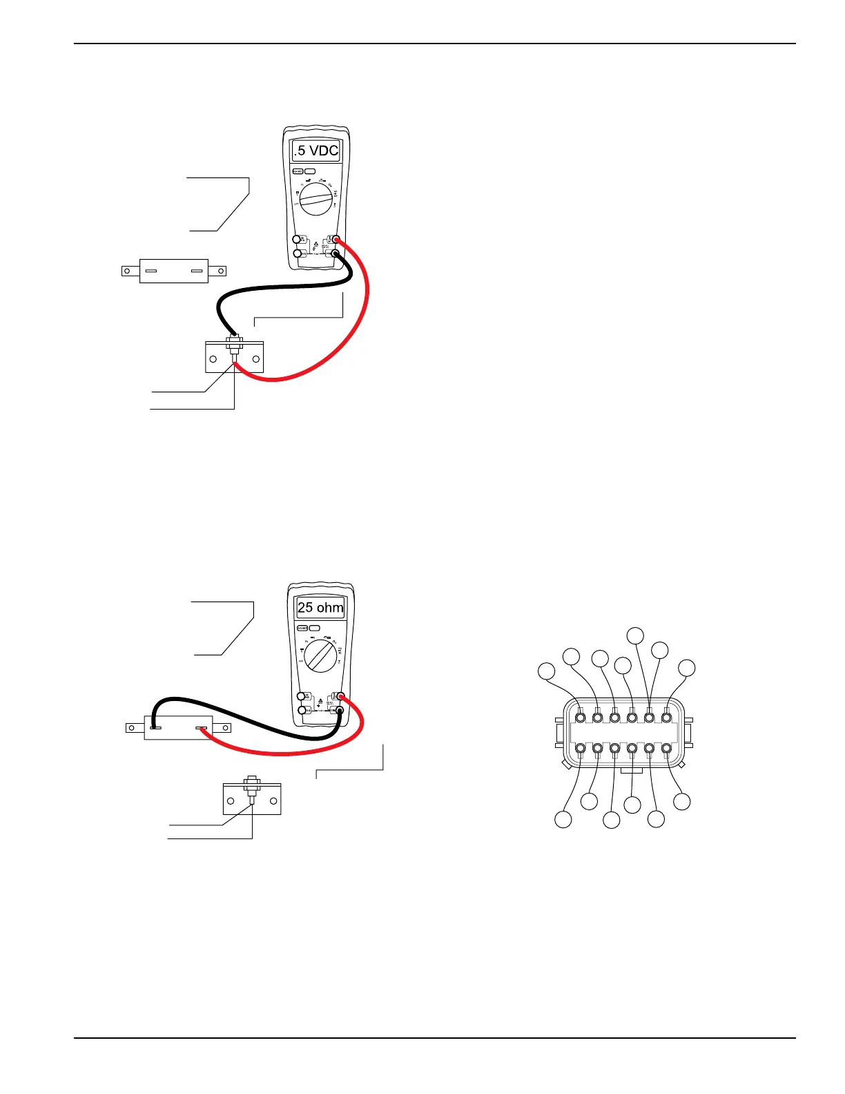
Figure 4-17. Diode Test Step 6
8. See Figure 4-18.
a. Connect one meter test lead to one terminal of
resistor R1.
b. Connect the other meter lead to the remaining
terminal of resistor.
c. Approximately 25 ohms should be measured.
Figure 4-18. Diode Test Step 9
9. Connect one meter test lead to the top terminal of
resistor R1.
10. Connect the other meter test lead to the ground
terminal.
a. Infinity or “Open” should be measured.
11. Connect the six pin connector, or wires to
terminals.
12. Connect the C1 connector.
13. Connect the two wires removed from resistor R1.
Results
1. If the diode or resistor failed any step it should be
replaced.
Test 9 – Test Stator
Procedure
1. Disconnect wires 11 and 44 from the 50 amp circuit
breaker.
2. Disconnect wire 22 from the 50 amp receptacle.
3. Disconnect connector C1. See Control Panel
Component Identification for connector location.
4. Set DMM to measure resistance.
5. Connect the meter test leads across stator leads
11 and 22.
a. Normal power winding resistance should be
measured.
6. Connect the meter test leads across stator leads
44 and 22.
a. Normal power winding resistance should be
measured.
See Figure 4-19 for the following steps.
7. Connect the meter test leads across stator leads
11S (pin 1) and stator lead 44S (pin 2) at the C1
connector female side.
a. Normal power winding resistance should be
measured.
Figure 4-19. C1 Connector, Female Side
8. Connect the meter test leads across stator leads
66A (pin 4) and stator lead 77A (pin 5) at the C1
connector female side.
a. Normal battery charge winding resistance
should be measured.
9. Connect the meter test leads across stator leads 2
(pin 6) and stator lead 6 (pin 7) at the C1 connector
female side.
$
7)2%
2%-/6%$
2
D2
4
14
WIRE 14
REMOVED
14
4
R1
004611
6543 21
789101112
2
77A
66A
55A
44S
OLDER
NEWER
22S
11S
0
4
77
66
55
6

 Loading...