Section 2 Engine DC Control System
16 Diagnostic Repair Manual
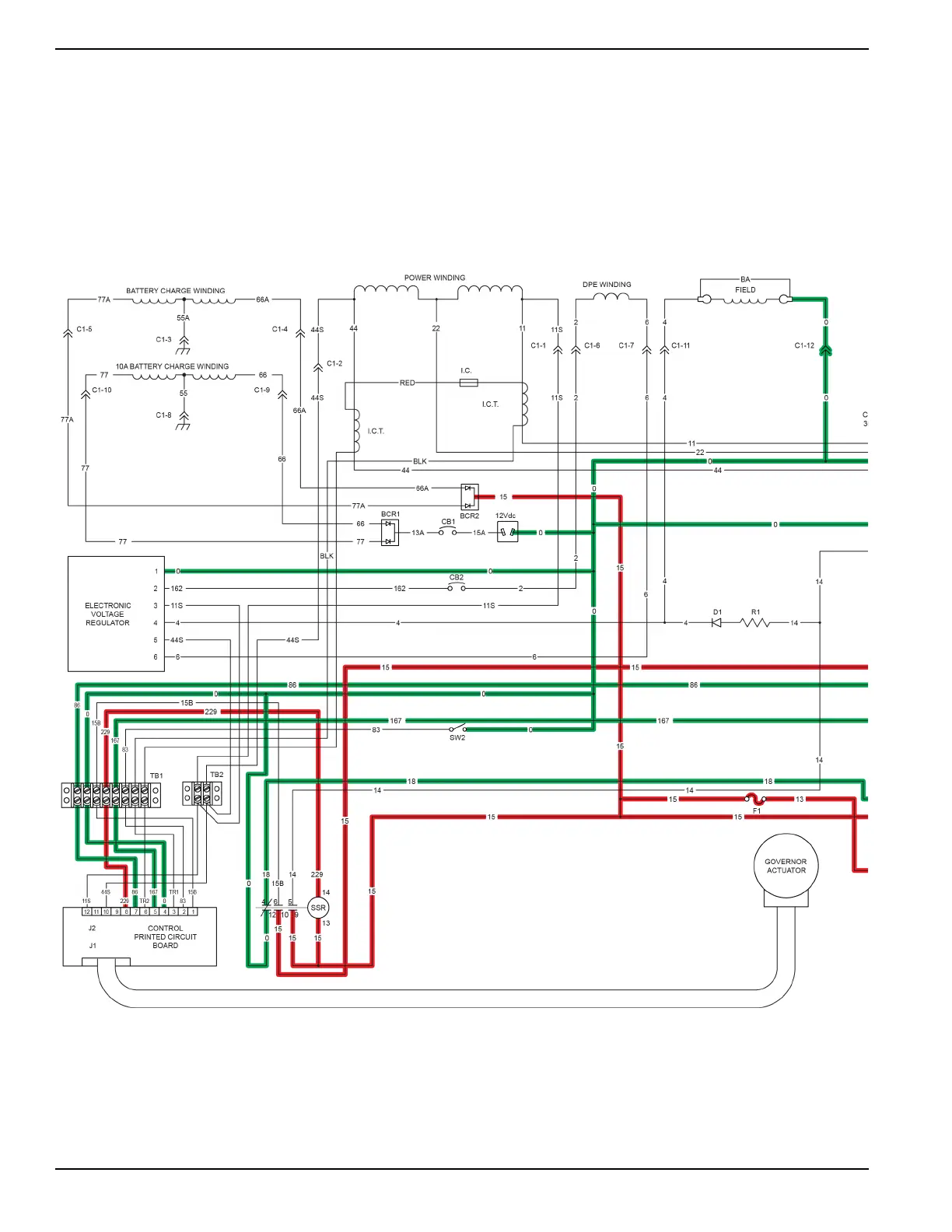
Circuit Condition - Stop
With the start-run-stop switch (SW1) placed in the STOP position, wire 167 is connected to wire 0 (frame ground). The
ground signal is supplied via wire 167 to the printed circuit board. The printed circuit board will internally open wire 229
from ground. This action will de-energize the start stop relay (SSR). With the SSR de-energized, wire 14 will no longer
have 12 VDC supplied to it through the relay. This de-energizes the fuel shutoff solenoid (FSS), stopping fuel to the
engine. With the SSR de-energized, wire 18 will now be connected to wire 0.
This action will ground the magnetos out through wire 18 causing loss of spark to the engine. With the loss of fuel and
loss of spark the engine will shutdown.

 Loading...