EasyManuals Logo
Home>Generac Power Systems>Portable Generator>GP Series

Generac Power Systems GP Series Diagnostic And Repair Manual

Generac Power Systems GP Series
98 pages
To Next Page IconTo Next Page
To Previous Page IconTo Previous Page
Page #16 background imageLoading...
Page #16 background image
Section 2 Engine DC Control System
12 Diagnostic Repair Manual
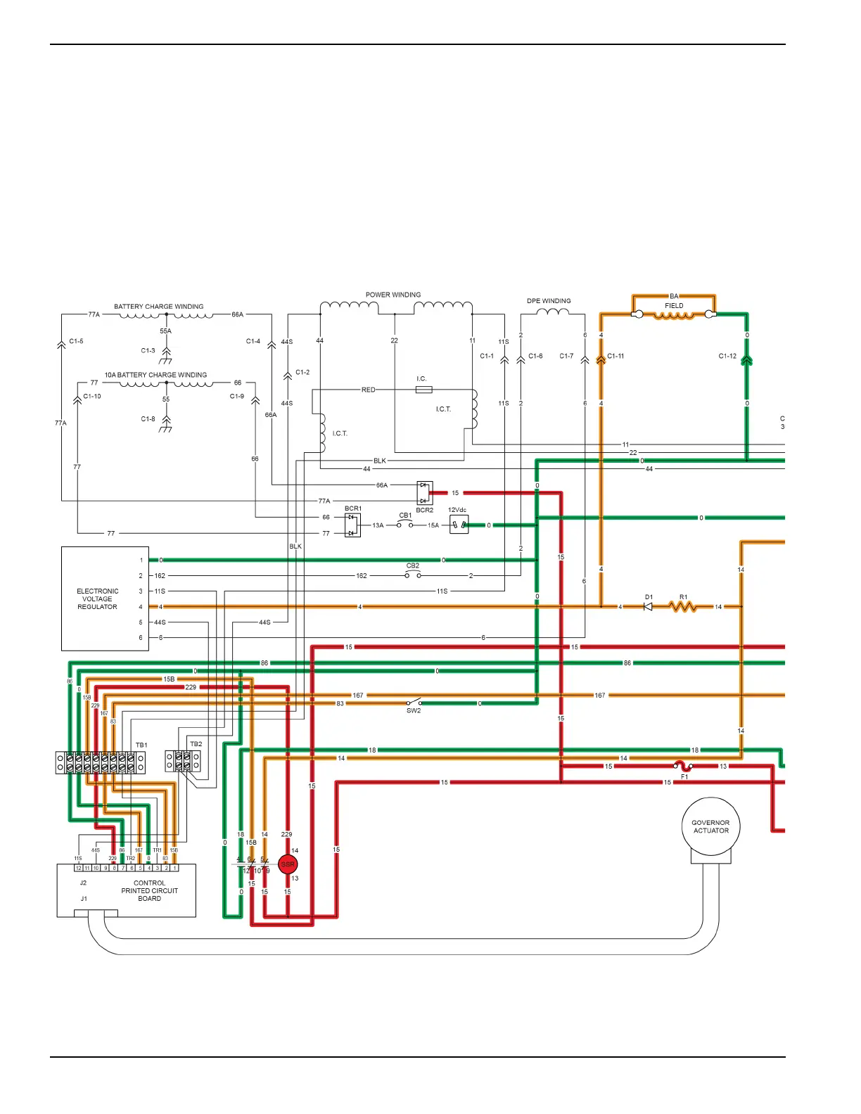
Circuit Condition - Start
With the start-run-stop switch (SW1) held in the START position, wire 17 is internally closed to ground via wire 0. By
grounding wire 17, current is allowed to flow through the SCR and energize the SCR coil. The SCR contacts internally
close wire 13 to wire 16. Wire 16 then delivers battery voltage to the starter contactor (SC) on the starter motor (SM).
The SC is energized and the contacts close, delivering battery voltage to the starter motor and the engine will start
cranking.
004577

Table of Contents

Other manuals for Generac Power Systems GP Series

Questions and Answers:

Question and Answer IconNeed help?

Do you have a question about the Generac Power Systems GP Series and is the answer not in the manual?

Generac Power Systems GP Series Specifications

General IconGeneral
BrandGenerac Power Systems
ModelGP Series
CategoryPortable Generator
LanguageEnglish

Related product manuals