Section 4 AC Diagnostic Tests
56 Diagnostic Repair Manual
If the engine will not start, remove and inspect the spark
plug. If the spark plug is wet, look for the following:
• Overchoking
• Excessively rich fuel mixture
• Water in fuel
• Intake valve stuck open
• Needle/float stuck open
If the spark plug is dry look for the following:
• Leaking carburetor mounting gaskets
• Intake valve stuck closed
• Inoperative fuel pump
• Plugged fuel filter(s)
• Varnished carburetor
If the engine starts hard or will not start, look for the
following:
• Physical damage to the AC generator. Check the
rotor for contact with the stator.
• Starting under load. Verify all loads are
disconnected or turned off before attempting to
crank and start the engine.
• Check that the choke is working properly.
1. Remove fuel line at carburetor and verify that there
is an adequate amount of fuel entering the carbu-
retor.
2. Remove the float bowl and check to see if there is
any foreign matter in bottom of carburetor bowl.
3. The float is plastic and can be removed to access
the needle for cleaning.
4. Carburetor cleaner can be used to clean the rest of
the carburetor before assembly.
5. After cleaning carburetor with an approved
carburetor cleaner, blow dry with compressed air
and assemble.
Shelf life of gasoline is 30 days. Proper procedures need
to be taken prevent fuel from varnishing over time. Use a
fuel stabilizer to ensure that the fuel remains fresh.
Results
If carburetor is varnished, clean or replace.
Refer to Flow Chart.
Test 40 – Valve Adjustment
Adjusting Valve Clearance
The valve lash must be adjusted correctly in order to
provide the proper air/fuel mixture to the combustion
chamber.
Adjust valve clearance with the engine at room
temperature. The piston should be at top dead center
(TDC) of its compression stroke (both valves closed).
An alternative method is to turn the engine over and
position the intake valve fully open (intake valve spring
compressed) and adjust the exhaust valve clearance.
Turn the engine over and position the exhaust valve fully
open (exhaust valve spring compressed) and adjust the
intake valve clearance.
The correct clearance for intake and exhaust valves is
0.002-0.004 inch (0.05-0.1 mm).
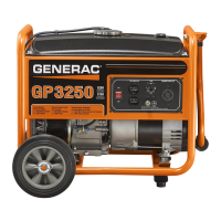
Figure 4-50. Adjusting Valve Clearance
1. See Figure 4-50. Loosen the rocker arm jam nut.
Use a 10mm allen wrench to turn the pivot ball stud
while checking the clearance between the rocker
arm and valve stem with a feeler gauge.
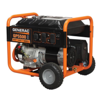
2. When clearance is correct, hold the pivot ball stud
with the allen wrench and tighten the rocker arm
jam nut to the specified torque with a suitable
wrench. After tightening the jam nut, check valve
clearance again to verify it did not change.
Torque Specification Rocker Arm Jam Nut:
168 in-lbs (19 Nm)
Figure 4-51. Tightening the Jam Nut
Install Rocker Arm Cover
1. Use a new rocker arm cover gasket. Install the
rocker arm cover and retain with four screws.
Results
Adjust valves to specification and repeat test. If problem
continues, refer to flow chart.

 Loading...