Section 4 AC Diagnostic Tests
46 Diagnostic Repair Manual
3. Start the generator.
a. The amp reading on the meter should be
approximately 0.2 Amps.
b. Apply full load to the generator.
c. The amp reading should increase.
d. Normal ranges at full load can be 3-7 amps,
but can get as high as 10 amps depending on
the state of charge of the battery.
Results
1. If amperage was measured between 0.2 to 10
Amps in step 2 and step 3, the charging system is
working.
2.
If no amperage was measured, check the meter fuses
and verify the functioning of the meter. If meter is
good and no current is measured refer to flow chart.
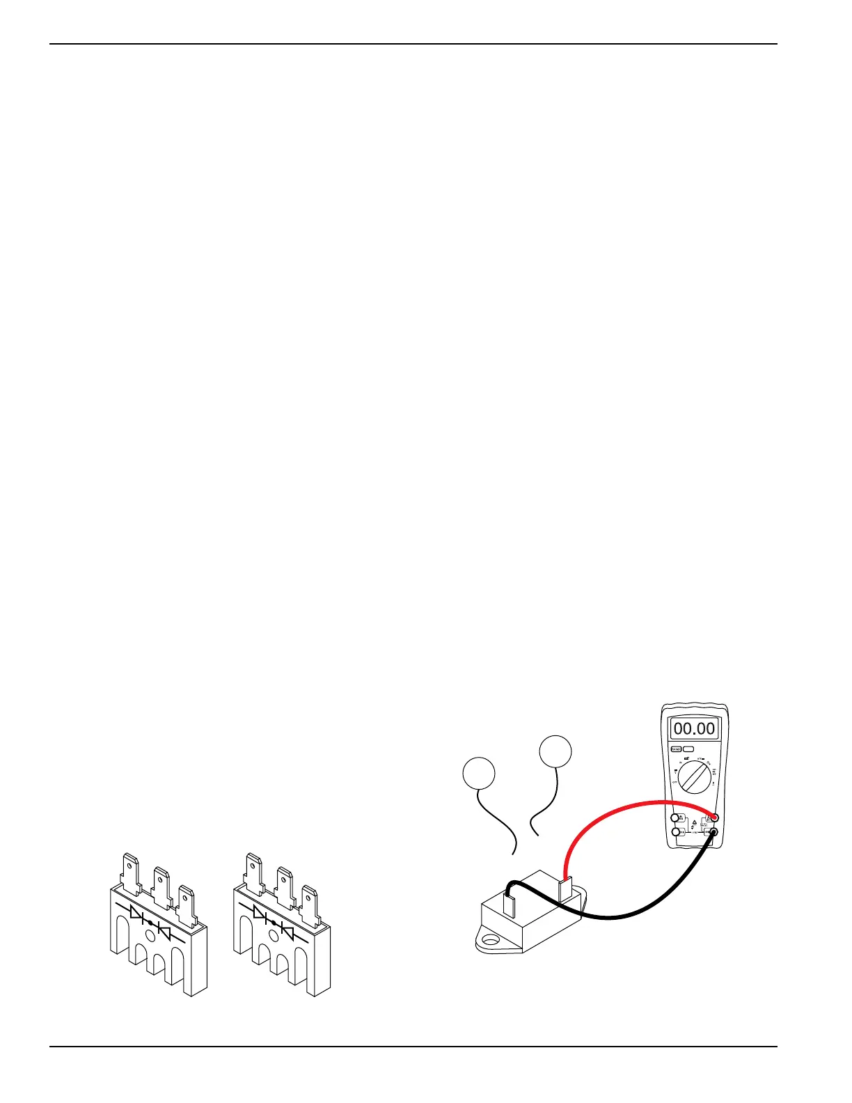
Test 19 – Check Battery Charge
Rectifier (BCR2)
Procedure
1. Disconnect all wires from battery charge rectifier 2
(BCR2).
2. Set the DMM to the Diode Test range.
3. Connect the negative (-) test lead to the center
terminal of BCR2.
4. Connect the positive (+) test lead to an outer
terminal.
a. The meter should measure approximately 0.5
volts.
5. Connect the positive test lead to the other outer
terminal.
a. The meter should measure approximately 0.5
volts.
6. Connect the positive (+) test lead to the center
terminal of BCR2.
7. Connect the negative (-) test lead to an outer
terminal.
a. The meter should measure Infinity.
8. Connect the negative test lead to the other outer
terminal.
a. The meter should measure Infinity.
Figure 4-26. Battery Charge Rectifier
Short to Ground
9. Set the DMM to measure resistance.
10. Connect the positive (+) test lead to the case
housing of BCR2.
11. Connect the negative (-) test lead to an outer
terminal.
a. The meter should measure Infinity.
12. Connect the negative test lead to the BCR center
terminal.
a. The meter should measure Infinity.
13. Connect the negative test lead to the remaining
outer BCR terminal.
a. The meter should measure Infinity.
Results
1. If any of the previous steps failed, replace BCR2.
2. If BCR2 tests good, refer back to the flow chart.
Test 20 – Check 10 Amp Circuit
Breaker
Procedure
1. Set DMM to measure resistance.
2. Locate the 10 Amp circuit breaker (CB1) in the
control panel. See Control Panel Component
Identification for circuit breaker location.
3. See Figure 4-27. Disconnect wire 15A and wire
13A from the circuit breaker.
4. Connect one meter test lead to one terminal of the
circuit breaker.
5. Connect the other meter test lead to the remaining
terminal on the circuit breaker.
a. Continuity should be measured.
Figure 4-27. Testing 10 Amp Breaker
10A CIRCUIT BREAKER (CB1)
13A
15A

 Loading...