Section 4 AC Diagnostic Tests
50 Diagnostic Repair Manual
Results
If Continuity was not measured in step 13 replace the
starter contactor relay. If all steps passed refer back to
flow chart.
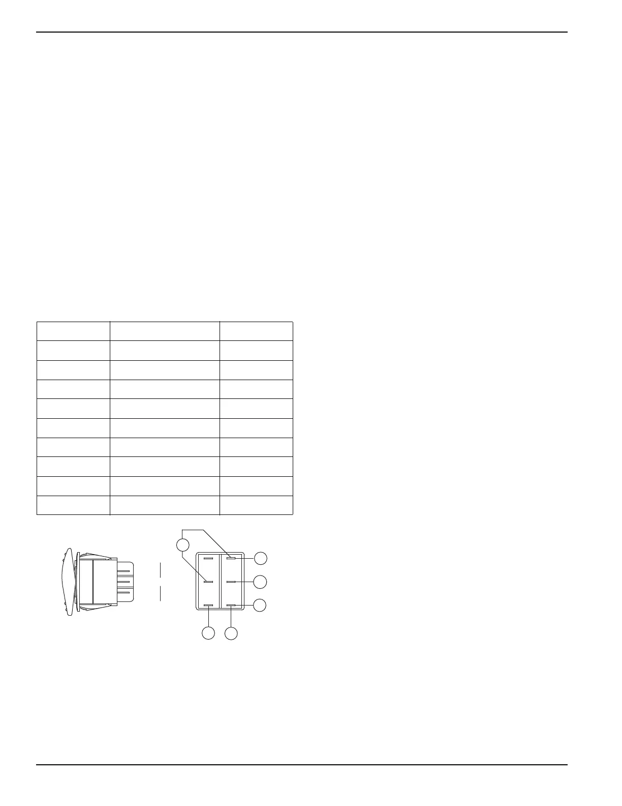
Test 27 – Check Start-Run-Stop
Switch (SW1)
Procedure
1. Set DMM to measure resistance.
2. Remove all wires from the start-run-stop switch
(SW1).
3. Use the chart below to check the condition of the
start-run-stop switch.
4. Connect one meter test lead to one terminal and
the other meter test lead to the other terminal.
5. With meter leads connected activate the switch to
START, STOP or RUN and follow the chart.
6. Connect all wires to the switch.
Figure 4-35. Start-Run-Stop Switch (SW1)
Results
If the switch fails any part of the test procedure replace
the switch.
Test 28 – Check Start-Run-Stop
Switch (SW1) Wiring
Procedure
1. Set DMM to measure resistance.
2. Remove wire 17 from the starter contactor relay
(SCR).
3. Connect one meter test lead to wire 17.
4. Remove wire 17 from the start-run-stop switch
(SW1).
5. Connect the other meter test lead to wire 17.
a. Continuity should be measured.
6. See Figure 4-35. Remove wire 0 from both
positions on the start-run-stop switch (SW1).
7. Connect a meter test lead to each wire 0.
a. Continuity should be measured.
8. Connect one meter test lead to one wire 0 and
connect the other meter test lead to frame ground.
a. Continuity should be measured.
9. Set DMM to measure DC voltage.
10. Remove wire 15 from the start-run-stop switch
(SW1).
11. Connect the positive meter test lead to wire 15.
12. Connect the negative meter test lead to frame
ground.
a. 12 VDC should be measured.
Results
Repair or replace any wiring that did not have continuity.
If voltage was not measured in step 12 repair wiring
between the starter contactor relay (SCR) and the start-
run-stop switch (SW1).
If all steps passed, repair or replace wire 16 between the
starter contactor (SC) and the starter contactor relay
(SCR).
Test 29 – Check Ignition Spark
Procedure
A commercially available spark tester may be used to
test the engine ignition system. One can also be
purchased from Generac Power Systems (Part No.
0C5969).
1. Disconnect a high tension lead from a spark plug.
2. Attach the high tension lead to the spark tester
terminal.
3. See Figure 4-36. Ground the spark tester clamp by
attaching to the cylinder head.
CONDITION TERMINALS RESULT
STOP 5,4 OPEN
STOP 5,6 CLOSED
STOP 2,1 OPEN
STOP 2,3 CLOSED
RUN ALL CONDITIONS OPEN
START 5,4 CLOSED
START 5,6 OPEN
START 2,1 CLOSED
START 2,3 OPEN
167
STOP
0
15
15
17
4
5
6
1
2
3
RUN
START
0

 Loading...