Section 4 AC Diagnostic Tests
Diagnostic Repair Manual 39
a. Connect one meter lead to red. Connect the
remaining test lead to orange. Approximately
10 ohms should be measured.
b. Connect one meter lead to red. Connect the
remaining test lead to yellow. Approximately 10
ohms should be measured.
c. Connect one meter lead to red. Connect the
remaining test lead to brown. Approximately 10
ohms should be measured.
d. Connect one meter lead to red. Connect the
remaining test lead to black. Approximately 10
ohms should be measured.
e. Connect one meter lead to red. Connect the
remaining test to the stepper motor case.
Infinity should be measured.
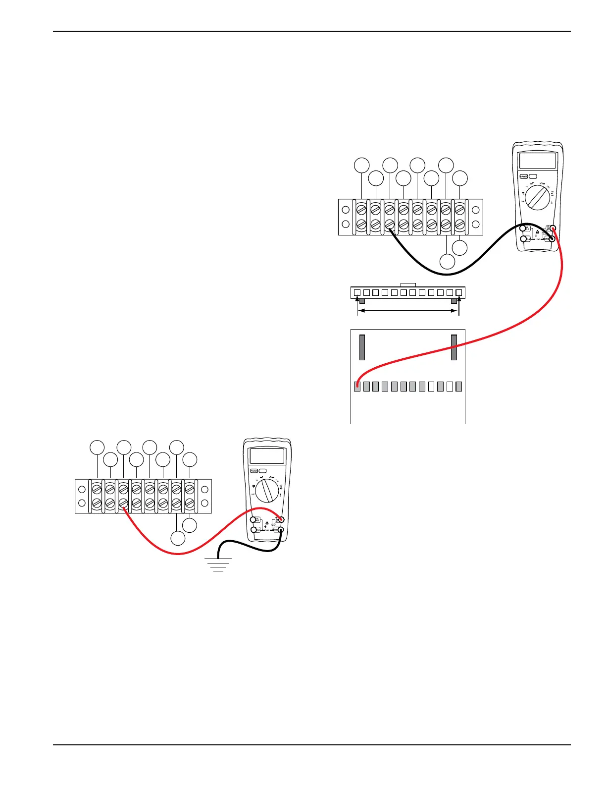
8. Set DMM to measure DC voltage.
9. See Figure 4-12.
a. Connect the positive meter test lead to wire
15B at terminal block 1 (TB1).
NOTE: Where terminal block is not present, place meter
test lead on the wire at the termination point. If
necessary, use a small paper clip to probe beside the
wire so as not to damage the terminal in the connector.
b. Connect the negative meter test lead to
ground.
c. Set the start-run-stop switch (SW1) to START.
d. If 12 VDC was measured proceed to step 8.
e. If voltage was not measured, proceed to
results.
Figure 4-12. Testing Wire 15B
10. Set DMM to measure resistance.
11. See Figure 4-13. Disconnect the J2 connector
from the printed circuit board.
a. Connect one meter test lead to pin location J2-
1 (wire 15B).
b. Connect the other meter test lead to wire 15B
at terminal block 1 (TB1).
c. Continuity should be measured.
NOTE: Verify the test probe connector is sharp and is
making contact the with the connector.
Results
1. If the stepper motor fails any part of step 5, replace
the stepper motor.
2. If step 7 fails repair or replace wire 15B between
the start stop relay (SSR) and terminal block TB1.
3. If the stepper motor passes all steps replace the
printed circuit board.
Figure 4-13. Testing J2-1
Test 6 – Wire Continuity
Procedure
1. Set DMM to measure resistance.
2. Remove the six pin connector from the voltage
regulator.
3. See Figure 4-11. Connect one meter test lead to
wire 0 in the six pin connector removed from the
voltage regulator.
4. Connect the other test lead to the ground terminal
in the control panel.
a. Continuity should be measured.
5. See Figure 4-11. Connect one meter test lead to
wire 162 in the six pin connector removed from the
voltage regulator.
6. Remove wire 162 from the excitation circuit
breaker (CB1).
7. Connect the other meter test lead to wire 162.
a. Continuity should be measured.
TERMINAL
BLOCK
(TB1)
12.00
86 15B
167
BLK
0 229
83
BLK
TR2
TR1
TB1
00.00
86 15B
167
BLK
0 229
83
BLK
TR2
TR1
J2-1 J2-12
004603

 Loading...