Section 4 AC Diagnostic Tests
64 Diagnostic Repair Manual
IMPORTANT NOTE: Before attempting to measure
Insulation resistance, first disconnect and Isolate all
leads of the winding to be tested. electronic components,
diodes, surge protectors, relays, voltage regulators, etc.,
can be destroyed if subjected to high megger voltages.
Hi-Pot Tester
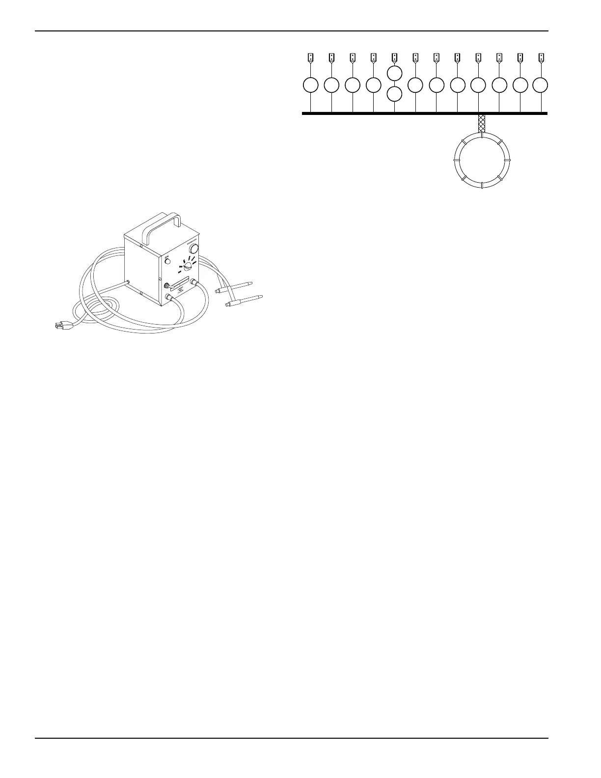
A hi-pot tester is shown in
Figure 4-63
. The model shown
is only one of many that are commercially available. The
tester shown is equipped with a voltage selector switch
that permits the power supply voltage to be selected. It
also mounts a breakdown lamp that will illuminate to
indicate an insulation breakdown during the test.
Figure 4-63. One Type of Hi-Pot Tester
Stator Insulation Resistance Test
Units with air-cooled engines are equipped with center
tapped AC power windings, an excitation or DPE
winding, a center tapped battery charge winding and a 10
Amp center tapped battery charge winding. Insulation
tests of the stator consist of testing all windings to
ground, testing between isolated windings, and testing
between parallel windings. Figure 4-64 is a pictorial
representation of the various stator leads on units with
air-cooled engine.
Testing All Stator Windings To Ground
1. Disconnect stator output leads wire 11 and wire 44
from the generator 50A circuit breaker.
2. Remove stator output lead wire 22 from the neutral
terminal on the back of the 50A outlet.
3. Disconnect the C1 connector from the bottom of
the control panel. See Control Panel Component
Identification. The C1 connector is on the right
when facing the control panel.
4. Connect the terminal ends of wires 11, 22, and 44
together. Make sure the wire ends are not touching
any part of the generator frame or any terminal.
Figure 4-64. Stator Assembly Leads
5. Connect the red test probe of the Hi-Pot tester to
the joined terminal ends of stator leads 11, 22, and
44. Connect the black tester lead to a clean frame
ground on the stator can. With tester leads
connected in this manner, proceed as follows:
a. Turn the hi-pot tester switch OFF.
b. Plug the tester cord into a 120 volt AC wall
socket and set its voltage selector switch to
“1500 volts”.
c. Turn the tester switch ON and observe the
breakdown lamp on tester. DO NOT APPLY
VOLTAGE LONGER THAN 1 SECOND. After
one (1) second, turn the tester switch OFF.
If the breakdown lamp comes on during the one-second
test, the stator should be cleaned and dried. After
cleaning and drying, repeat the insulation test. If, after
cleaning and drying, the stator fails the second test, the
stator assembly should be replaced.
6. Now proceed to the C1 connector (female side –
just removed). Each winding will be individually
tested for a short to ground. Insert a large paper
clip (or similar item) into the C1 connector at the
following pin locations:
Next refer to steps 5a through 5c of the hi-pot procedure.
Example: Insert paper clip into pin 1, hi-pot from pin 1
(wire 11S) to ground. Proceed to pin 2, pin 3, etc. through
pin 10.
Item Wire Number Winding
A 11 Power Winding
B 44 Power Winding
C 22 Power Winding
D 11S Sense Lead Power
E 44S Sense Lead Power (Older Style)
F 22S Sense Lead Power (Newer Style)
G 55A Battery Charge
H 66A Battery Charge
I 77A Battery Charge
J 2 Excitation
K 6 Excitation
L 55 10 Amp Battery Charge
M 66 10 Amp Battery Charge
N 77 10 Amp Battery Charge
A
B C D
E
F
G H I J K L M
004714

 Loading...