Section 2 Engine DC Control System
Diagnostic Repair Manual 15
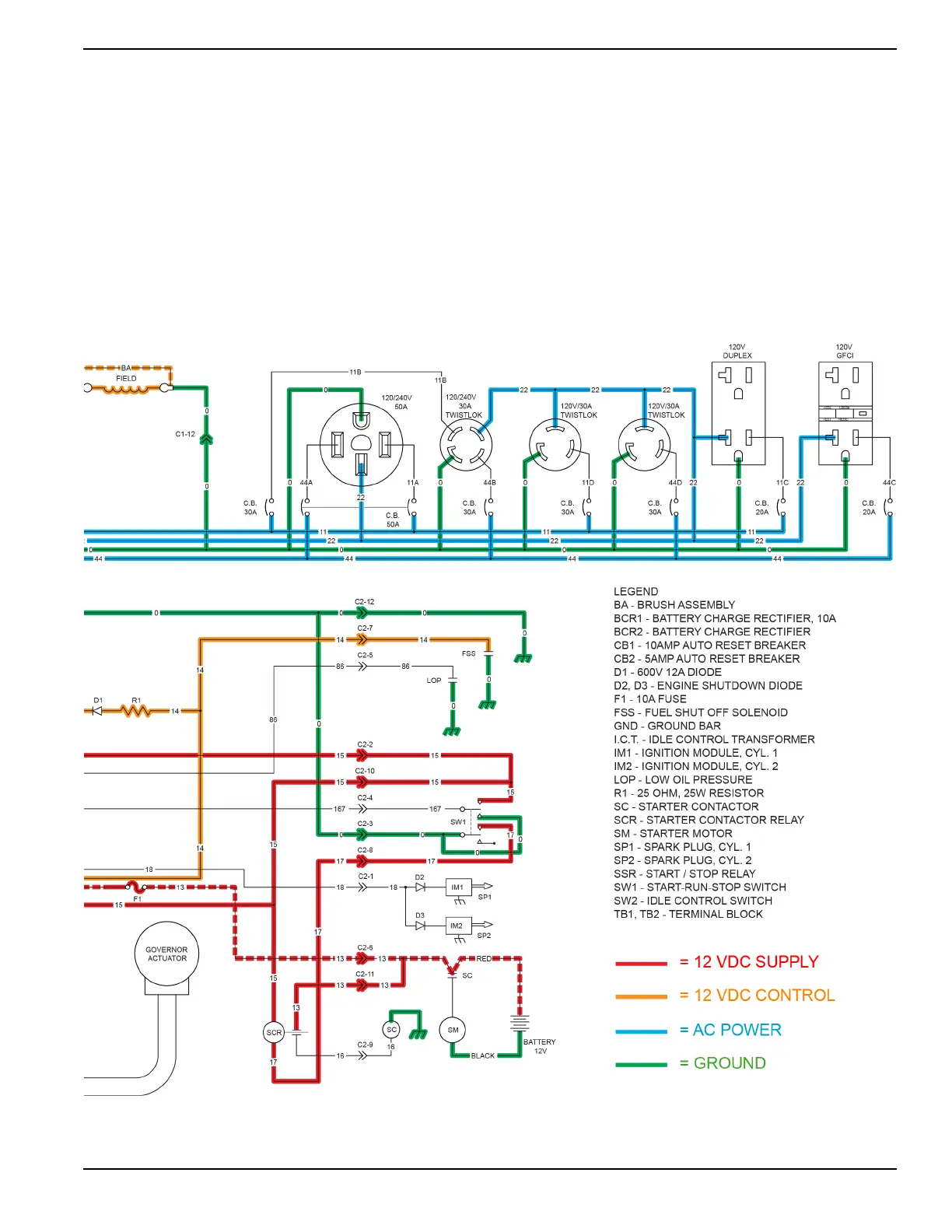
The printed circuit board is supplied with AC voltage from wires 11S and 44S. This voltage, frequency signal is used by
the printed circuit board for governor control operation.
When the idle control switch (SW2) is activated to the ON position, wire 83 from the printed circuit board will be
connected to wire 0 (frame ground). There are two idle control transformers (ICT) that sense current flow off the main
power windings. The voltage signal from the ICT’s connect to the printed circuit board via wires TR1/TR2 and are used
for sensing load on the generator. With no-load on the generator there is no current supplied from the ICT’s and the
engine will run at a lower RPM. When a load is applied to the generator, the ICT’s supply a voltage signal to the printed
circuit board and the engine RPM will be increased to running RPM, approximately 3600 RPM.

 Loading...