Section 2 Direct Excitation (Brush Type)
Diagnostic Repair Manual 7
Troubleshooting Flowcharts
Introduction
Use the Flow Charts in conjunction with the AC Diagnostic Tests . Test numbers used in the flow charts correspond to
the numbered tests in the AC Diagnostic Tests . The first step in using the flow charts is to identify the correct problem
on the following pages. For best results, perform all tests in the exact sequence shown in the flow charts.
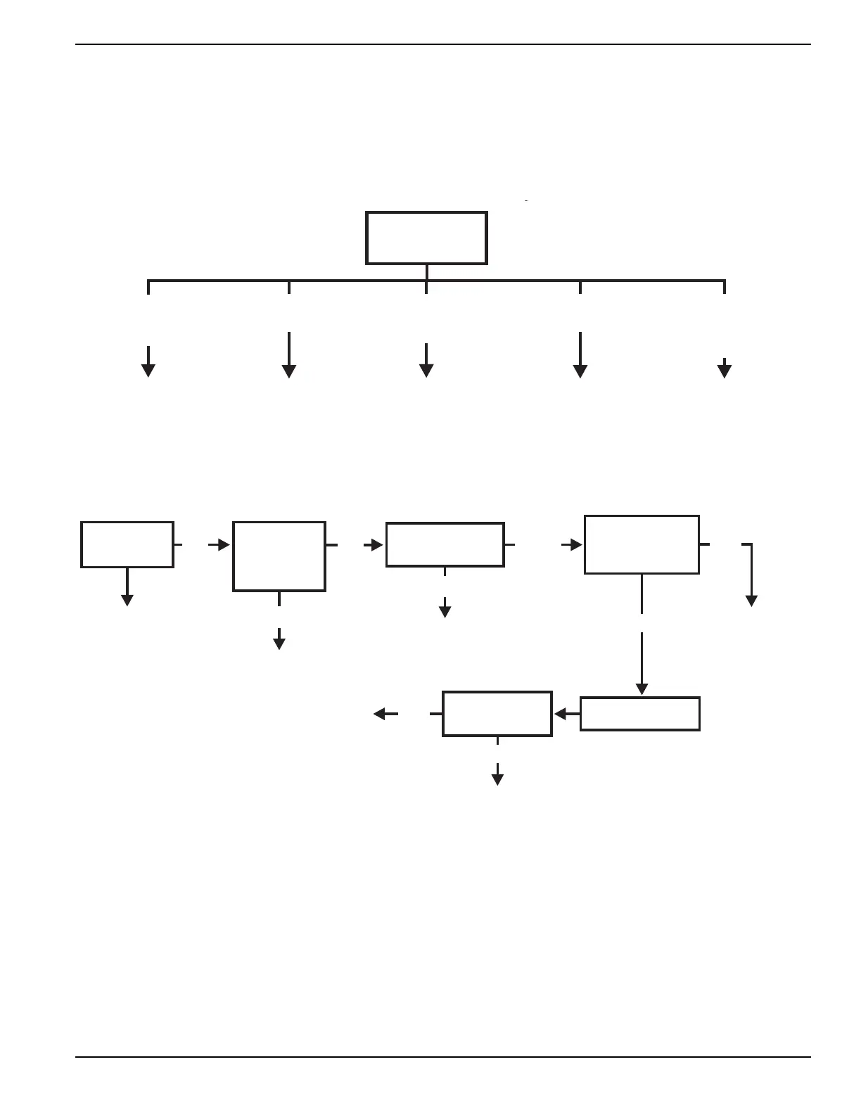
If Problem Involves AC Output (Brush Type)
Problem 5 – Generator Produces Zero Voltage or Residual Voltage
GO TO PROBLEM 6 GO TO PROBLEM 5GO TO PROBLEM 8 GO TO PROBLEM 7
VOLTAGE &
FREQUENCY BOTH
HIGH OR LOW
FREQUENCY GOOD
VOLTAGE HIGH
ZERO VOLTAGE
ZERO FREQUENCY
FREQUENCY GOOD,
LOW OR RESIDUAL
VOLTAGE
TEST 1 - CHECK
NO LOAD VOLTAGE
& FREQUENCY
NO LOAD VOLTAGE &
FREQUENCY GOOD -
VOLTAGE/FREQUENCY
FALLS OFF UNDER LOAD
p
VERIFY ROTOR IS SPINNING,
GO TO PROBLEM 5
BAD
BAD
GOOD
TEST 2 – CHECK
MAIN CIRCUIT
BREAKER
RESET TO “ON”
OR REPLACE IF BAD
REPLACE COMPONENT
AS NEEDED
REPLACE COMPONENT
AS NEEDED
TEST 3 – CHECK
CONTINUITY OF
RECEPTACLE PANEL
REPLACE
ALTERNATOR
REPLACE AUTOMATIC
VOLTAGE REGULATOR
TEST 4 – FIXED
EXCITATION
TEST/ROTOR AMP
DRAW TEST
ON
GOOD
STOP TESTING
GOOD
BAD
RE-CHECK VOLTAGE
AT RECEPTACLE
PANEL
TEST 13 –
TEST 120/240
CHANGEOVER
SWITCH
(IF EQUIPPED)
REPLACE SWITCH
ON
BAD