Diagnostic Repair Manual 17
Section 4 EFI Engine Control Diagnostic Tests
Basic EFI Theory
Electronic Fuel Injection was first introduced to
automobiles in the late 1960s. EFI is not new, as its roots
were firmly established many years ago. However, EFI is
fairly new to portable generators.
Basic Open-Loop Theory
EFI uses a solenoid valve called an injector to meter fuel
delivery. The typical system uses 1 injector per cylinder.
When the solenoid is energized, fuel sprays out into the
intake valve port. Fuel is delivered to the injector by a
high-pressure electric pump at approximately 36 psi. Fuel
delivery is controlled by the injector which is cycled by
the ECU. The ECU (Engine Control Unit) produces a
signal to open the injector for a certain length of time
depending on engine conditions transmitted by the
sensors. The longer the injector is open, the more fuel is
injected. As engine load increases, the injector open time
is increased to match the increased airflow. This ECU
output signal is called the injector pulse width. The longer
the pulse width, the more fuel is injected. In a typical
Open-Loop EFI system, there is no oxygen (O
2
) sensor
to monitor or change the fuel delivery.
Engine Requirements
The correct proportion of fuel is required to be mixed with
the incoming air for efficient operation. Most generator
engines utilize a ratio of approximately 14.7 parts air to 1
part fuel for the no load to full load power band. This is
the chemically correct ratio which results in the lowest
average emissions and best power. A rich condition is
characterized by an excess of fuel and a lean condition is
characterized by an excess of air or lack of fuel.
As the load is increased, up to capacity, the throttle is
opened and as airflow increases fuel flow must increase
to match it.
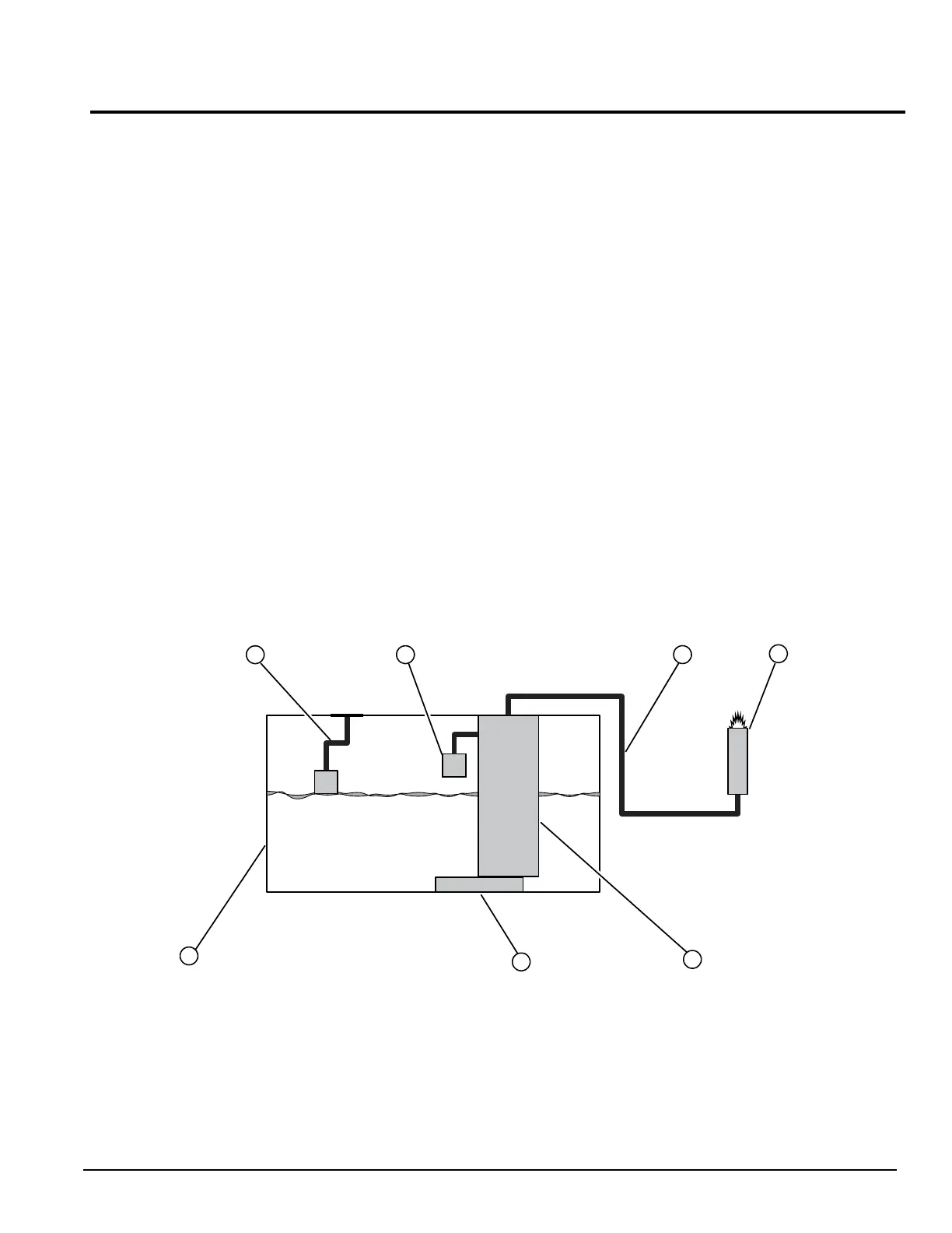
Fuel System
See Figure 4-1. EFI fuel systems consist of a tank,
pump, regulator, and injector. Fuel is drawn from the tank
by the pump which steps up the pressure to
approximately 36 psi. Fuel pressure is controlled by the
fuel pressure regulator located in the fuel pump,
discharging unused fuel back into the tank. When load
demand increases, there is sufficient fuel available. The
injector is sealed with an O-ring and has a 2-pin electrical
plug to carry switching current to the solenoid windings.
When energized, the solenoid core is pulled back,
allowing fuel to spray out in a fine, conical pattern.
Figure 4-1. Return-less System
A. Fu
el Gauge / Float C
. Pre
ssure Line
E. Fu
el Pump
G.
Fuel Tank
B.
Pre
ssure Regulator D.
F
uel Injector F.
F
uel Filter