Section 5 Engine Diagnostic Tests
32 Diagnostic Repair Manual
Test 25 – Check Engine / Cylinder
Leak Down Test / Compression Test
General Theory
Most engine problems may be classified as one, or a
combination of the following:
• Will not start
• Starts hard
• Lack power
• Runs rough
• Vibration
• Overheating
• High oil consumption
General Theory
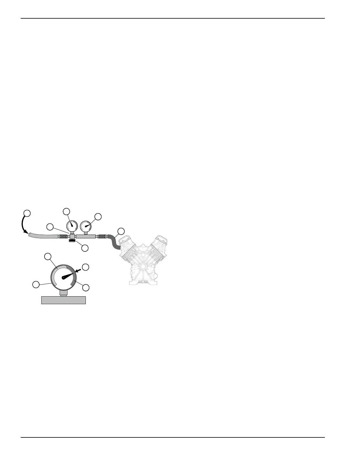
The Cylinder Leak Down Tester checks sealing
(compression) ability of engine by measuring air leakage
from combustion chamber. Compression loss can
present many different symptoms. This test detects the
section of the engine where the fault lies before
disassembling the engine. Figure 5-16 represents a
standard tester available on the market.
Figure 5-16. Cylinder Leakdown Tester
Procedure
1. Shut off the fuel supply.
2. Remove spark plug.
3. Gain access to flywheel.
4. Remove valve cover.
5. Rotate engine crankshaft until the piston reaches
top dead center (TDC). Both valves should be
closed.
6. Lock flywheel at top dead center.
7. Attach cylinder leak down tester adapter to spark
plug hole.
8. Connect an air source of at least 90 psi to the leak
down tester.
9. Adjust regulated pressure on gauge to 80 psi.
10. Read right hand gauge on tester for cylinder
pressure. 20 percent leakage is normally
acceptable. Use good judgment, and listen for air
escaping at carburetor, exhaust, and crankcase
breather. This determines where the fault lies.
Results
•
Air escapes at carburetor – check intake valve.
• Air escapes through exhaust – check exhaust
valve.
• Air escapes through breather – check piston rings.
• Air escapes from cylinder head – replace head
gasket.
Check Compression
To check engine compression, remove spark plug. Insert
an automotive type compression gauge into the spark
plug hole. Crank engine until there is no further in
pressure. The highest reading obtained is engine
compression pressure.
Minimum Allowable Compression Pressure Cold
Engine – 60 psi
If compression is poor, look the following causes:
• Loose cylinder head bolts
• Failed cylinder head gasket
• Burned valves or valve seats
• Insufficient valve clearance
• Warped cylinder head
• Warped valve stem
• Worn or broken piston ring(s)
• Worn or damaged cylinder bore
• Broken connecting rod
• Worn valve seats or valves
• Worn valve guides
NOTE: Refer to Engine Service Manual Part Number
0C1103A for further engine service information on the
410cc engine.
NOTE: Refer to Engine Service Manual Part Number
10000016870 for further engine service information on
the 426cc engine.
A. Compressed air in
B. Air pressure regulator
C. Inlet gauge pressure set point
D. Outlet gauge pressure
E. To spark plug hole
F. Regulator adjustment knob
G. Outlet gaug
e
H.
Red range indicates unacceptable leakage
I. Needle indicates minimal air leakage
J. Green range indicates acceptable leakage
A
C
B
D
E
F
I
J
G
H