Section 5 Engine Diagnostic Tests
28 Diagnostic Repair Manual
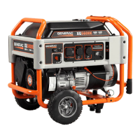
Figure 5-3. Starter Circuit Voltage Drop Test
Connections
7. If voltage drop is greater than the above, based on
the circuit or component, clean or replace the failed
connection or component. If voltage drop test
results are within the above, based on the circuit or
component, refer back to the flowchart.
Test 17 – Check START-RUN-STOP
Switch (410/426cc Engine)
General Theory
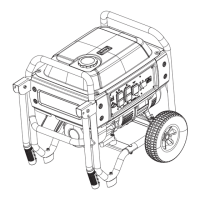
See Figure 5-4. The START-RUN-STOP switch utilizes
ground potential to start and shutdown the engine. When
the switch is actuated to START, positive 12 VDC is
delivered to the starter contactor, allowing the engine to
crank. Once positive 12 VDC is removed, by releasing
the switch to the RUN position, it disengages the starter
allowing the engine to operate. When switch is actuated
to STOP, ground is applied to the magneto coil(s) which
inhibits spark from occurring.
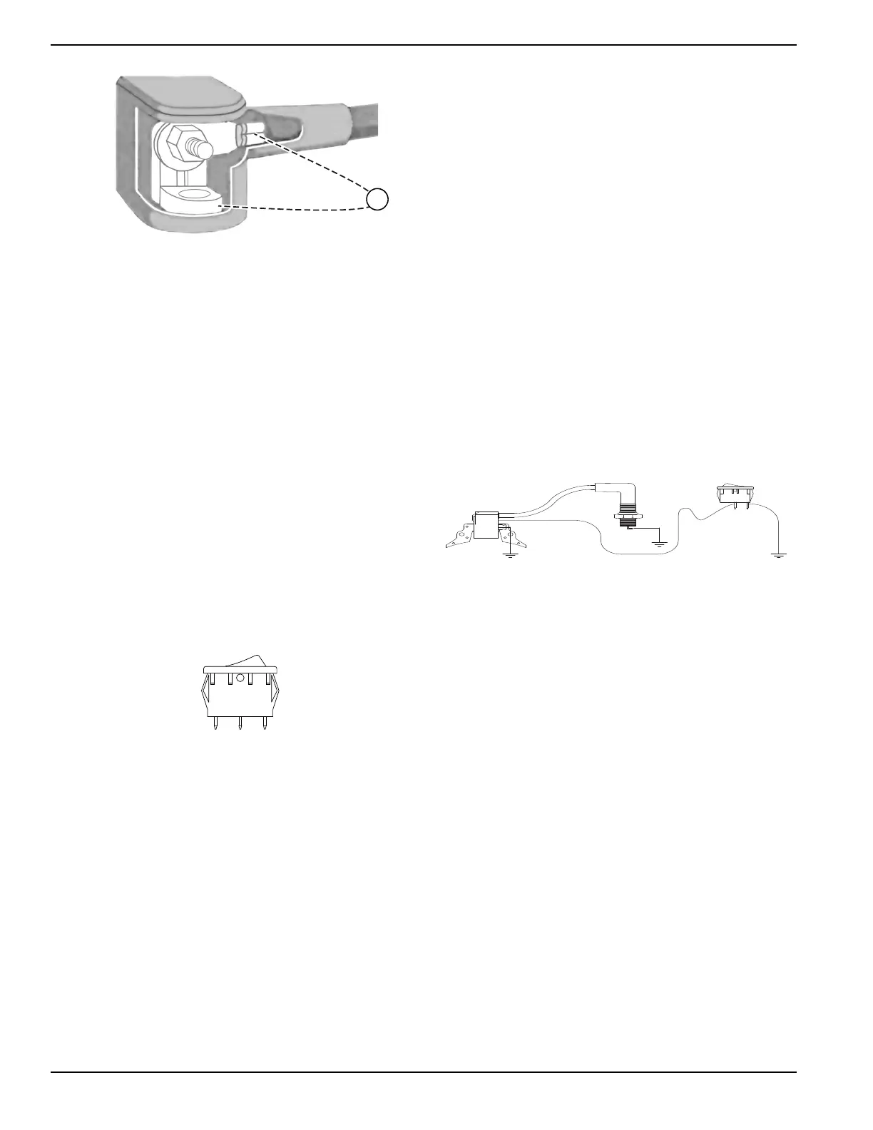
Figure 5-4. START-RUN-STOP Switch
Procedure
1. Set a digital multimeter (DMM) to measure
resistance.
2. Remove all wires from START-RUN-STOP Switch
(SW1).
3.
Connect one meter lead to Terminal 2 and the other
meter lead to Terminal 1. Actuate switch to START
position. CONTINUITY should be measured.
4. Actuate switch to the STOP position. INFINITY
should be measured.
5. Keep one meter lead on Terminal 2 and connect
the other meter lead to Terminal 3. Actuate switch
to the STOP position. CONTINUITY should be
measured.
6. Actuate switch to START position. INFINITY
should be measured.
7. Connect one meter test lead to disconnected Wire
0 from Terminal 2 and connect the other meter test
lead to the positive post of the battery, 12 VDC
should be measured. If voltage is not measured,
repair or replace Wire 13A between the starter
contactor and the START-RUN-STOP switch.
8. Connect all wires to the switch.
Results
1. If any other readings were measured, replace
START-RUN-STOP switch.
2. Refer to flow chart.
Test 18 – Test OFF-ON Switch
General Theory
The OFF-ON switch applies a ground to the shutdown
harness (Wire 18). Applying ground to the harness
grounds out the magneto and inhibits spark.
Procedure
1. See Figure 5-5. Disconnect Point A from switch.
Figure 5-5. OFF-ON Switch Test Points
2. Connect one meter lead to male connector on
switch and the other meter test lead to a clean
frame ground.
3. Actuate switch back and forth between ON and
OFF. CONTINUITY should only be measure in the
OFF position.
Results
1. If switch failed Step 3, replace OFF-ON switch.
2. If OFF-ON switch is good, refer to flow chart.
Test 19 – Check Starter Motor
The following conditions affect starter motor
performance:
1. Binding or seizing in starter motor bearings.
2. A shorted, open, or grounded armature.
a. Shorted, armature (wire insulation worn an
d
wire
s touching),. indicated by low or no RPM.
b. Open armature (wire broken), indicated by lo
w
or
no RPM and excessive current draw.
c. Grounded armature (wire insulation worn and
wire touc
hing armature lamination or shaf
t),
in
dicated by excessive current draw or no RPM.
3. A defective starter motor switch.