Section 1 Brushless Capacitor Excitation
2 Diagnostic Repair Manual
Operation
Startup
When the engine is started, residual/permanent
magnetism from the rotor induces a voltage into (a) the
stator AC power windings, and (b) the stator excitation or
DPE windings. In an “On-speed” (engine cranking)
condition, residual/permanent magnetism is capable of
creating approximately one to three Volts AC.
On-Speed Operation
As the engine accelerates, the voltage that is induced
into the stator windings increases rapidly, due to the
increasing speed at which the rotor operates.
Field Excitation
An AC voltage is induced into the stator excitation (DPE)
windings. The DPE winding circuit is completed to the
capacitor where the capacitor is charged until the AC
voltage peaks and then discharges as the AC voltage
starts to decay. The charging and discharging causes a
voltage to be induced back into the rotor which will
produce voltage. The greater the current flow through the
rotor windings, the more concentrated the lines of flux
around the rotor become. The more concentrated the
lines of flux around the rotor that cut across the stationary
stator windings, the greater the voltage that is induced
into the stator windings. Initially, the AC power winding
voltage is low, but as the capacitor is charged and
discharged this relationship between the rotor and the
capacitor is what will regulate voltage at a desired level.
AC Power Winding Output
A maintained voltage is induced into the stator AC power
windings. When electrical loads are connected across
the AC power windings to complete the circuit, current
can flow in the circuit.
NOTE: The voltage of a brushless capacitive discharge
generator will start low and increase as load is applied.
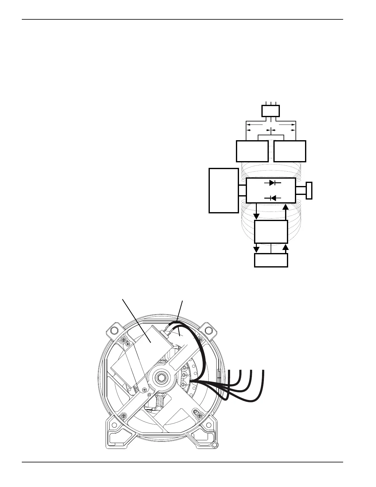
Figure 1-3. Generator Operating Diagram
Figure 1-4. Alternator Configuration A
CAPACITOR
003817
STATOR
EXCITATION
WINDING
STATOR
POWER
WINDING
STATOR
POWER
WINDING
MAGNETIC
FIELD
MAGNETIC
FIELD
MLB = MAIN LINE
CIRCUIT BREAKER
ROTOR
TO LOAD
MLB
ENGINE -
DIRECT
DRIVE
120 VAC 120 VAC
240 VAC
WIRE 2
WIRE 6
11 22 33 44
CAPACITOR 47μf (440 VAC)