Section 1 AC Diagnostic Tests
Diagnostic Repair Manual 11
13. While the unit is running connect one jumper wire
to the negative terminal of the battery and connect
the other jumper wire to the positive terminal.
14. Record voltage measured on Wires 2 and 6 on the
C1 female connector. Approximately 60 VAC
should be measured.
15. Set RUN-STOP switch to STOP.
16. Set DMM to measure resistance.
17. Connect the meter test lead to one jumper wire and
connect the other meter test lead to the other
jumper wire to measure resistance of the brushes
and the rotor. See Rotor and Stator Resistance
Tables for resistance values. If the correct
resistance was not measured, remove brushes and
measure resistance across the slip rings. If
resistance is measured, inspect or replace
brushes. If resistance was NOT measured across
the slip rings, replace rotor.
18. Set DMM to measure DC amperage.
NOTE: Inspect the fuses in the meter to ensure test
results will be correct.
19. Connect one meter test lead to the positive jumper
wire.
20. Set RUN-STOP switch to RUN and start unit.
21. Connect the negative jumper wire to the negative
terminal on the battery and connect the other meter
test lead to the positive terminal.
NOTE: The meter should now be connected in series
with the positive jumper wire.
22. Record DC amperage measured. Approximately
0.22 DC amps should be measured.
NOTE: The DC voltage of the battery divided by the
resistance measured in Step 17 will give a calculated
amp draw.
23. Set RUN-STOP switch to STOP.
24. Repeat Step 21 while the unit is OFF. The DC
amperage measured should be the same as step
22 ± 0.10 DC amps.
25. Set DMM to measure resistance.
26. See Figure 2-3. Connect one meter test lead to
S15 and connect the other meter test lead to S15
on the female side of the C1 connector.
Approximately 0.5 to 1.5 Ohms should be
measured.
Results
1. If current was outside parameters in Steps 23 and
24, remove brushes and measure resistance.
2. If voltage was not measured in Step 8 at either the
receptacle or the stator connection terminal strip,
replace the alternator.
3. If voltage was not measured in Step 14, replace the
alternator.
4. If the correct resistance was not measured in Step
26, replace the alternator.
5. If the correct resistance was not measured in Step
17, replace the alternator.
6. If the correct voltage was measured in Step 8 and
Step 14 and the correct resistance was measured
in Step 26, replace the voltage regulator.
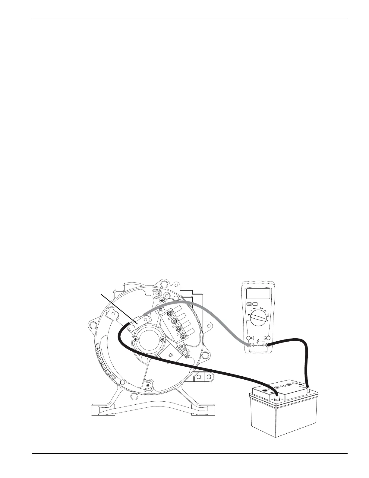
Figure 3-5. Jumper Wire and DMM Between Battery and Brush Assembly
0.2 Amps
BRUSH ASSEMBLY
12 VOLT
BATTERY
(-)
(+)