Plotter Adjustments 63
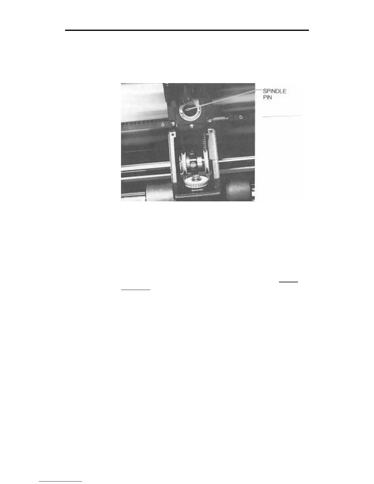
5. After the spindle initializes, note the position of the slot or
keyway in the side of the tool holder. Face the front of the
plotter, the spindle pin should be in the "nine o'clock" position.
If the pin is aligned correctly, proceed to a test cut, step 12. If
the spindle pin is not aligned correctly, go to the next step.
6. Locate the rear way collar clamp. Use an Allen wrench to
loosen the collar clamp. Be careful not to move the black
timing belt.
7. Rotate the rear way by hand until the spindle pin is properly
aligned at the 9:00 position. Tighten the clamp.
8. Turn the power off to unlock the theta axis.
9. Rotate the rear way by hand to make the spindle pin out of
alignment. Power up the plotter to the normal off-line state.
The spindle pin should return to the correct alignment. If not,
turn the plotter power off. Return to step 4.
Note: If needed, repeat steps 4 through 9 to obtain correct
alignment.