13
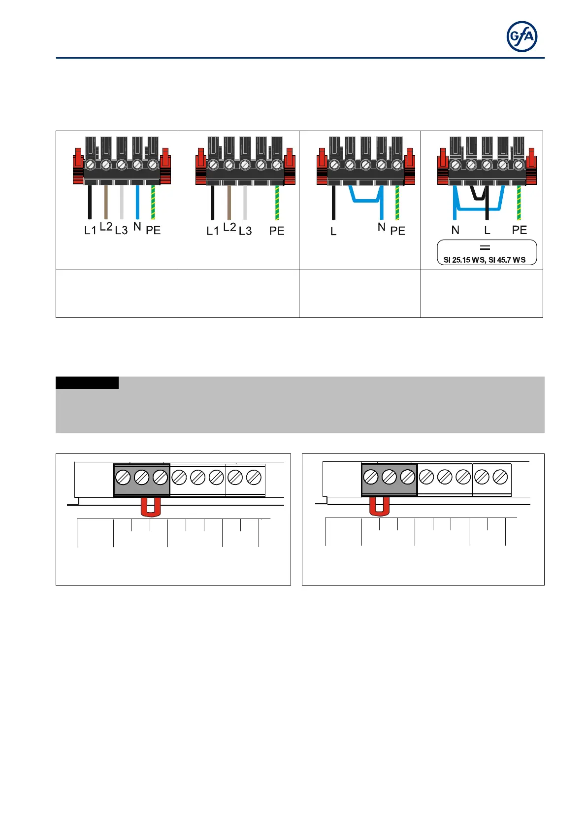
Mains supply
Before connecting, check whether a clockwise rotating field is present at the installation site. If not, create a
clockwise rotating field.
3~, N, PE
220–400 V / 50-60 Hz
3~, PE
220–400 V / 50-60 Hz
1~, N, PE, sym.
220– 230V / 50-60 Hz
1~, N, PE, asymmetrical
220–230 V / 50-60 Hz
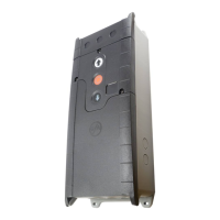
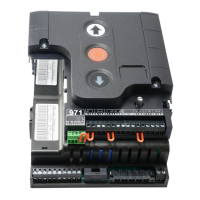
Position of the transformer bridge
The door control can be operated with different mains voltages (see figures below).
Ensure the correct position of the transformer bridge according to the mains voltage on site.
Damaging or destroying the product
The door control is always factory-set to the highest voltage.
Install the bridge as shown below.
20.1
1.5
1.8
1.9
20.2
1.6
20.3
1.7
230V
400V
20.1
1.5
1.8
1.9
20.2
1.6
20.3
1.7
230V
400V