Release 00 - 02/2008
Engine WBE 0701-WBE 0704
pag. 27
Service manual
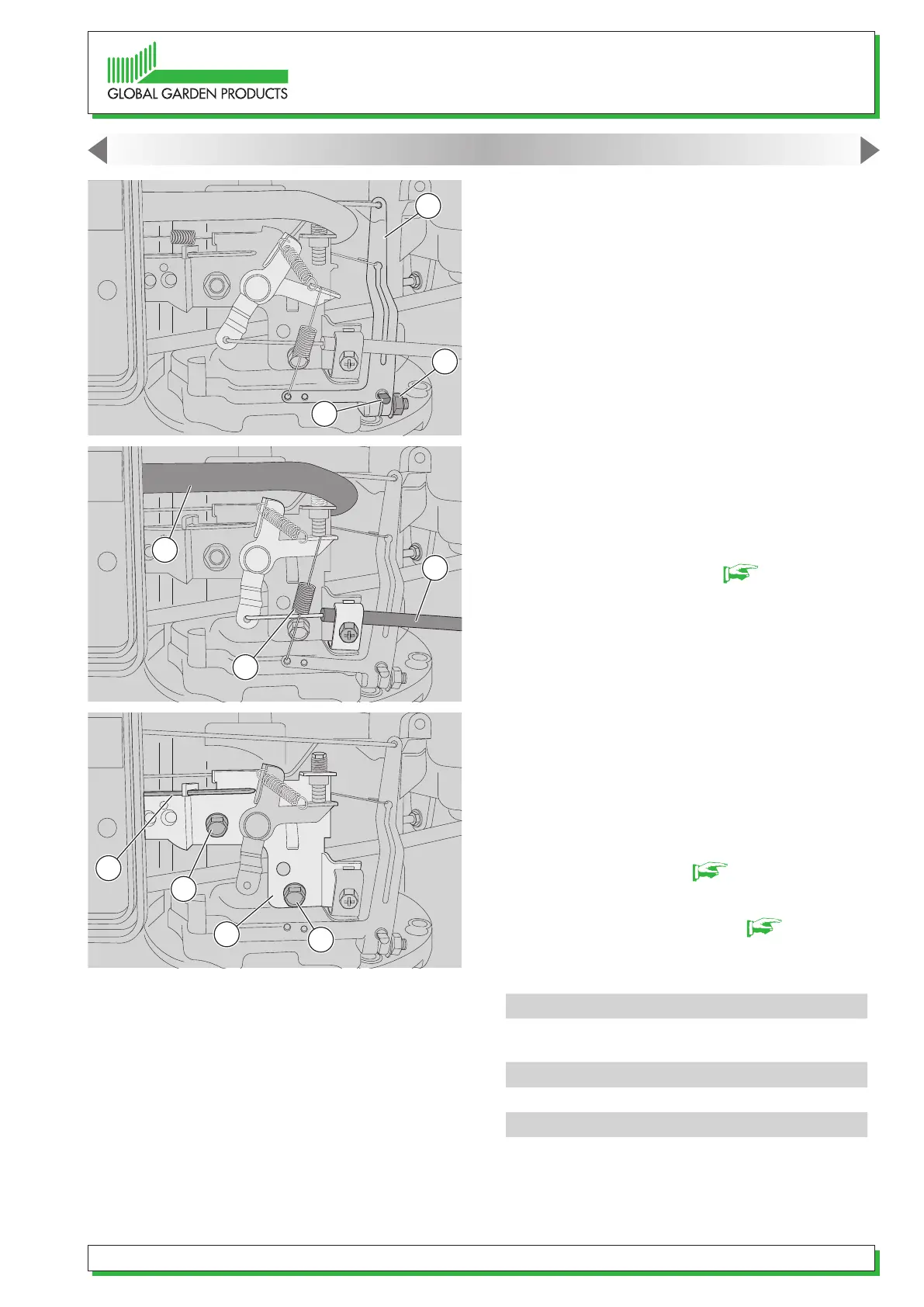
6 - If the above checks do not show any faults,
the phasing of the governor’s control lever (13)
with respect to the counterweight device must be
checked:
- stop the engine and move the accelerator control
to “FAST”;
- slacken off the control lever (14) locknut (13);
- without changing the lever (13) position determi-
ned by the spring (12) and tie-engine shaft (11), use
a screwdriver to turn pin (15) clockwise to the end
of its stroke and then lock the nut (14).
9.3. Replacing the lever support
1 - Position the choke lever to minimum (“SLOW”
position).
2 - Remove the carburettor [ 8.1].
3 - Disconnect the accelerator cable (3) and remo-
ve the breather pipe (16) and the spring (10).
4 - Disconnect the choke buttery wire (17) and
undo the two screws (18) securing the support (19)
to the engine.
5 - Perform the above operations in reverse order
when assembling.
6 - Ret the carburettor [ 8.1].
7 - Adjust the maximum speed [ 9.2].
Tightening torques
18
Support screw, governor
assembly
8-10 Nm
Technical information
Maximum speed (FAST)
2900 (±100) r.p.m.
Special equipment
6 Speed indicator
9. GOVERNOR SYSTEM OF THE CARBURETTOR
10
3
17
18
19
18
13
14
15
16
 Loading...