Series 8035XA Peak Power Sensors
2-2 Manual 21568, Rev. F, March 2008
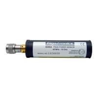
2.2.1 5, 25 and 50 Watt Peak Power Sensors
Power Sweep Calibration of the 5, 25 and 50 W Peak Power Sensors (80351A, 80352A and
80355A, respectively) require you to disconnect the high power attenuator before you connect
the sensor directly to the front panel calibrator connector. When power sweep calibration is
completed, reconnect the high power attenuator to the sensor.
Proper connector alignment is shown by small black arrows printed on the attenuator and
sensor labels. The serial number on the sensor housing and the serial number on the high
power attenuator should match. During manufacture, the frequency response of the attenuator
is calibrated and entered into the peak power sensor EEPROM as frequency calibration
factors. This technique improves the accuracy and repeatability of your measurements.
CAUTION
Do not exceed 200 mW (+23 dBm) Peak or Average. Excessive in-
put power will damage or destroy the power sensor element.
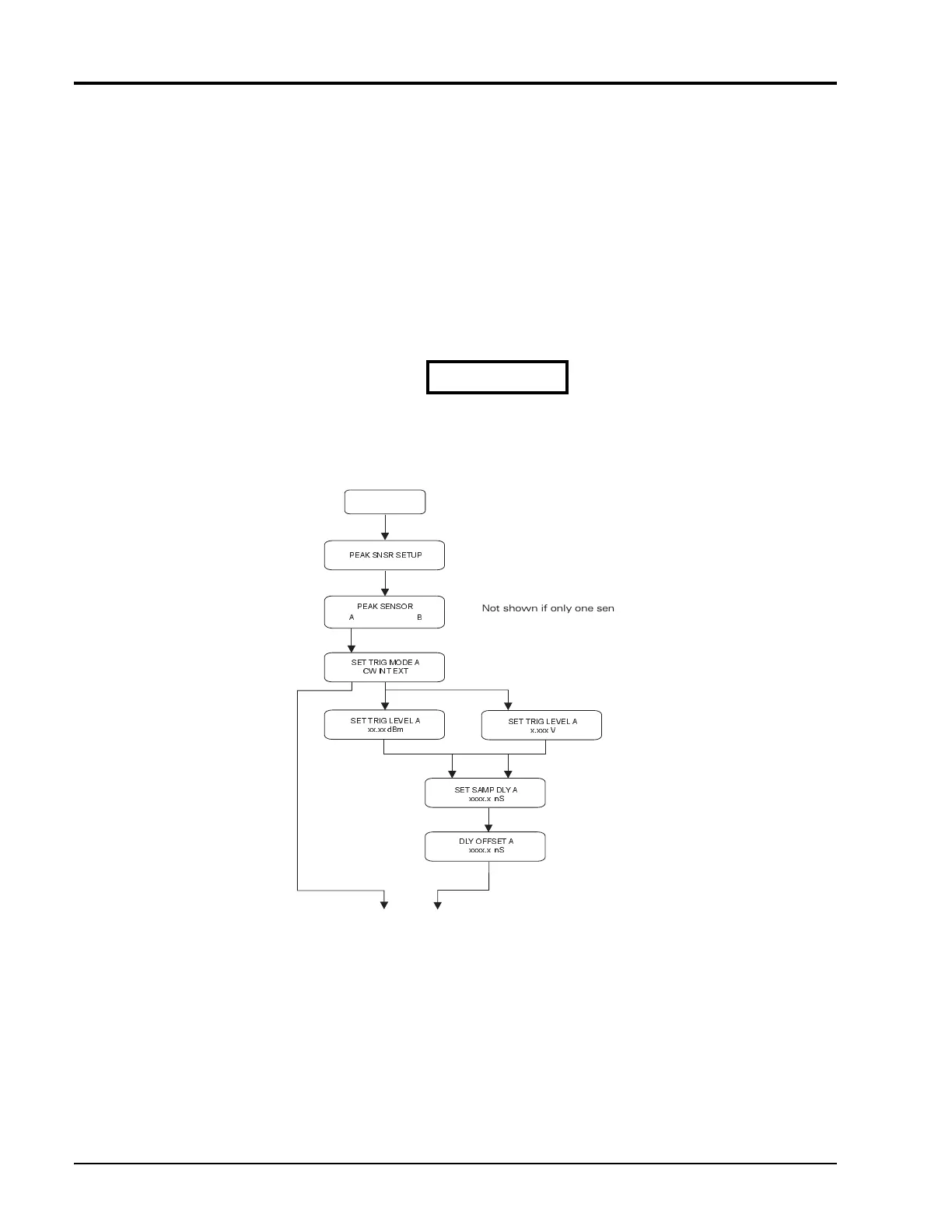
Figure 2-1: Sensor Setup Menu Tree
PEAK SNSR SETUP
PEAK SENSOR
A
B
Not shown if only one sensor is attached
or if the power meter is single-channel (8541)
SET TRIG MODE A
CW INT EXT
SET TRIG LEVEL A
xx.xx dBm
SET TRIG LEVEL A
x.xxx V
SET SAMP DLY A
xxxx.x nS
DLY OFFSET A
xxxx.x nS
SET UP
To default display


 To Next Page