Maintenance
Manual 21568, Rev. F, March 2008
A1TP1 should measure about -0.2V, and A1TP2 should measure about +0.2V with a 0 dB CW
input. If either of these voltages are absent, the element is probably bad and should be
replaced.
The following table lists problems that can occur with the sensor in the logical order that these
problems might become evident. Go to the first described symptom, and then follow the
instructions given in the section covering that symptom. Symptom descriptions assume that
everything preceding that symptom in the table is functioning properly.
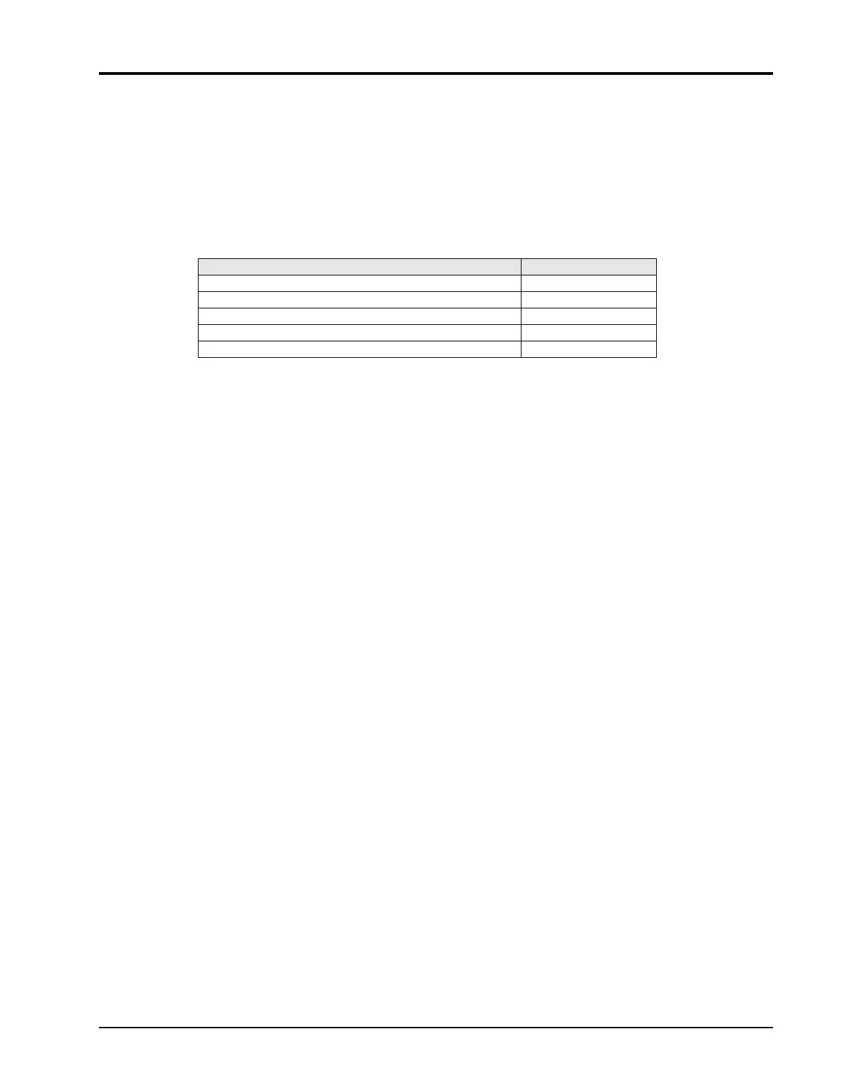
Table 5-1: Sensor Malfunction Symptoms
Symptom Section
Sensor is not recognized as being present 5.2.1
Will not calibrate / zero 5.2.2
INTernal will not trigger or level error 5.2.3
EXTernal will not trigger or level error 5.2.4
Delay error 5.2.5
In these procedures, the component prefix A1 designates parts located on the Analog PC
Board. The prefix A2 is for parts located on the Digital PC Board. Voltage levels at Monitor Out
and at test points are approximate. These values vary from sensor to sensor. To ensure that
proper levels are present, increase or decrease the measured input or trigger level. The
measured point should change correspondingly. Certain supplies (A1U3, 4, 5, 6, and A2U18
and A2 5 V line) are isolated by 10 ohm resistors which decouple noise and can act as fuses. If
one of these resistors (A1R108, 109, 110, 111, or 112, or A2R42 or A2R45) is open, replace
the corresponding tantalum capacitor (A1C51, 52, 53, 54, or A1C30 or A2C19).
 Loading...