Theory of Operation
Manual 21568, Rev. F, March 2008
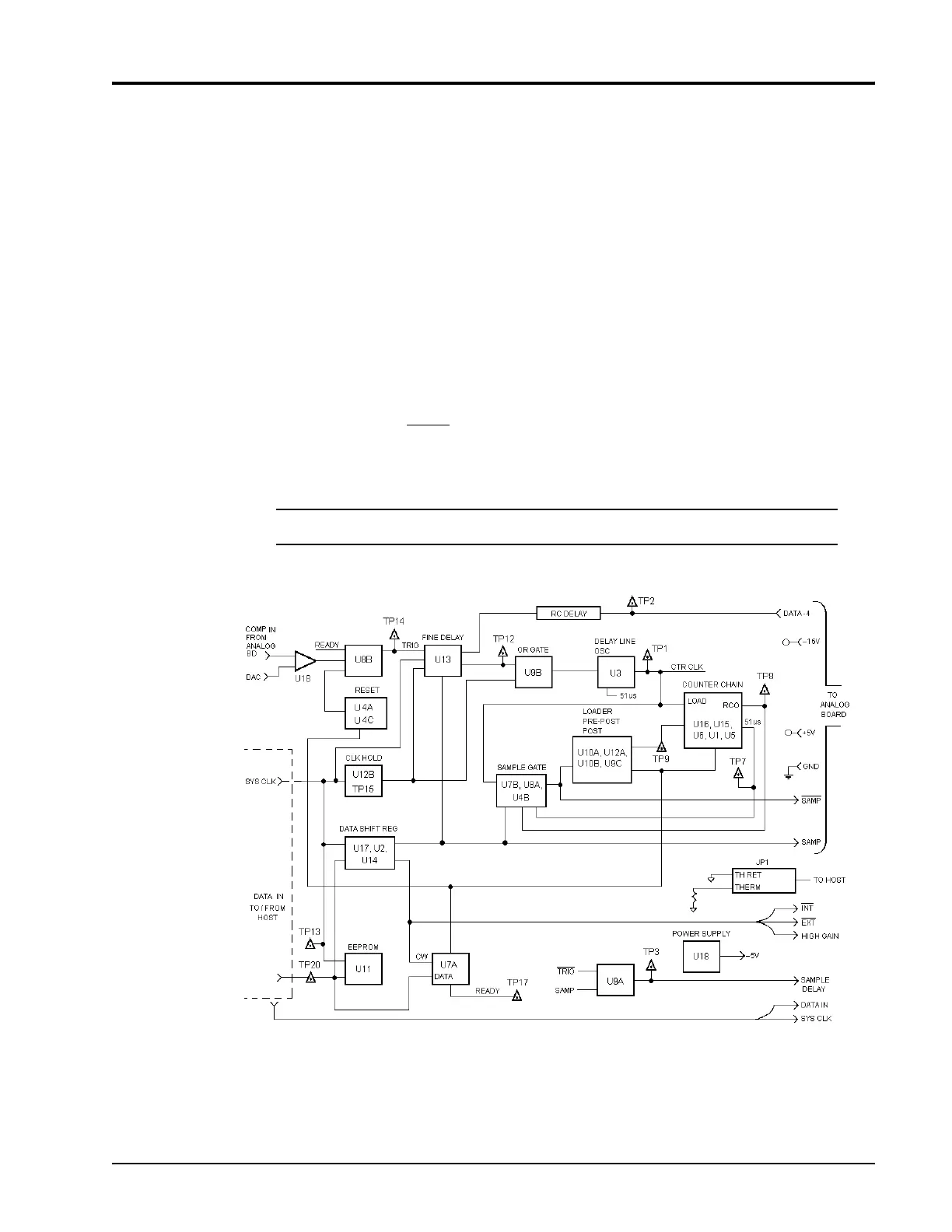
3.3 Digital Assembly Description
3.3.1 Overview
Refer to the Digital PC block diagram in Figure 3-4, and the Digital Timing Diagrams in Figures
3-5, 3-6 and 3-7.
The digital board provides the timing functions for delays between a small negative time (with
respect to either the video monitor, or the sampled pulse) and >100 ms. In the CW mode, the
digital board is not reset, but continues to generate clocks and samples at about 70 µs
intervals. In either the INTernal or EXTernal modes, an acquisition is requested by the host (the
power meter to which the sensor is connected is the host) which causes READY to be set.
When an input trigger is received, it is latched and delayed by a FINE delay, and then starts a
10-MHz clock. The clock increments a COARSE counter until it reaches FFFFF or all ones, and
then outputs a Ripple Carry Out (RCO) signal. This is latched as SAMPle, delayed by one
count, and then compared to the count of 51µs out of the counter to allow the SAMPle to be
51µs wide. Then the COARSE counter is reLOADed for about 5µs, the 10-MHz clock is
stopped for about 5µs, the
LOAD unasserted, and the TRIGger, SAMPle, and READY flip-flops
reset for about 1µs. A 48-bit serial stream provides the 80350A configuration information. When
the serial clock is running, CLKHOLD resets the TRIG loop and loads the counter.
*
NOTE: Over-score indicates a logic-NOT condition.
Figure 3-4: Digital PC Assembly Block Diagram
 Loading...