Series 8035XA Peak Power Sensors
4-2 Manual 21568, Rev. F, March 2008
4.3 Power Linearity Test
The linearity will be tested in a series of 10 dB steps over the range of the sensor. At low power
levels, the measurements will reflect the uncertainty due the noise and zeroing specifications.
Make a copy of the Performance Verification Data Sheets at the end of this chapter to record
the data from this test.
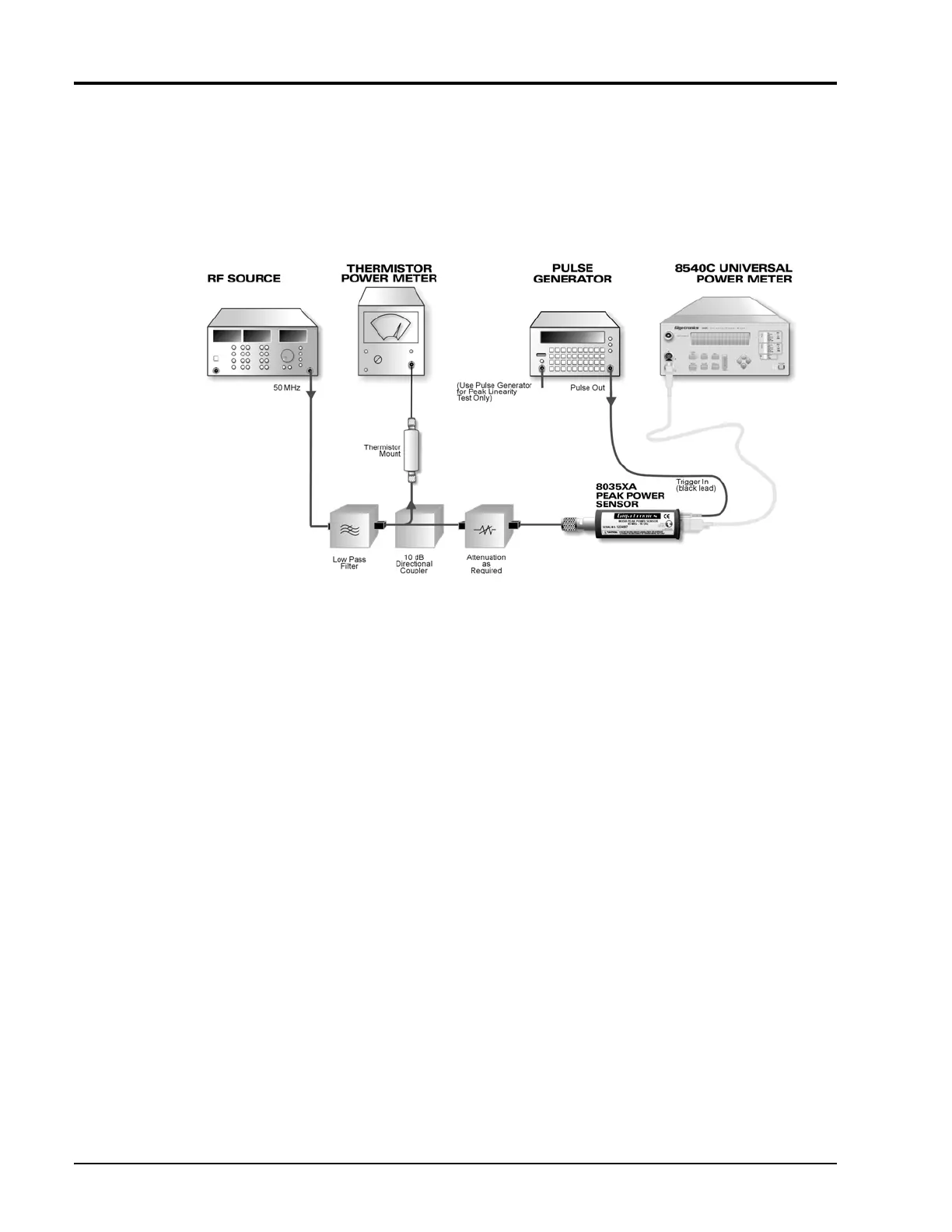
Figure 4-8: Power Linearity Test Setup
4.3.1 CW Linearity Test
1. Connect the test setup as shown in Figure 4-8. Set the RF source to 50 MHz. Be sure the sensor
has had at least 24 hours of warm-up time. To take accurate measurements, it is essential to take
out any drift that might occur.
a. Calibrate the Peak Power Sensor as described in the applicable Power Meter Operation and
Maintenance manual.
b. Place the peak sensor into the CW mode.
c. Set the power meter to display power in linear units (mW).
d. Set Averaging to 4.
e. Set the CW frequency to 50 MHz.
2. Start with no attenuation between the coupler and the Peak Power Sensor. Record results on the
first row of the linearity data recording sheet. If the sensor being tested is an 80351A, 80352A
or 80355A model, remove the attenuator from the sensor.
3. Turn the RF source off and zero the Peak Power Sensor by pressing [ZERO/CAL].
4. Zero the thermistor power meter.
5. Turn the RF source on.
 Loading...