Operation
Manual 21568, Rev. F, March 2008
2.3.8 Measuring Pulse Droop
Pulse characteristics such as droop, ripple, and overshoot can be measured quickly using
referenced measurements. This involves the use of the front panel REL key for the Series 8540
power meter users, or the CALC#:REF:COLL function for 58542 power meters.
1. Connect the 8035XA Peak Power Sensor to the power meter and the CALIBRATOR
output.
2. Press [CAL/ZERO] to calibrate the sensor to the meter.
3. Upon successful completion of power sweep calibration, connect the sensor to a pulsed signal
source. The power level must be above the trigger level.
4. Connect the 8035XA Detector Out and Sample Delay leads to a digital oscilloscope.
5. Set the sample delay (DLY
A
) to the t
1
position just after the rising edge as shown in Figure
2-15.
6. Press [REL]. The display should now read approximately 0.00 dBm or 100%.
7. Set the sample delay to the t
2
position just before the falling edge of the pulse.
The display is now reading the pulse-top amplitude variation.
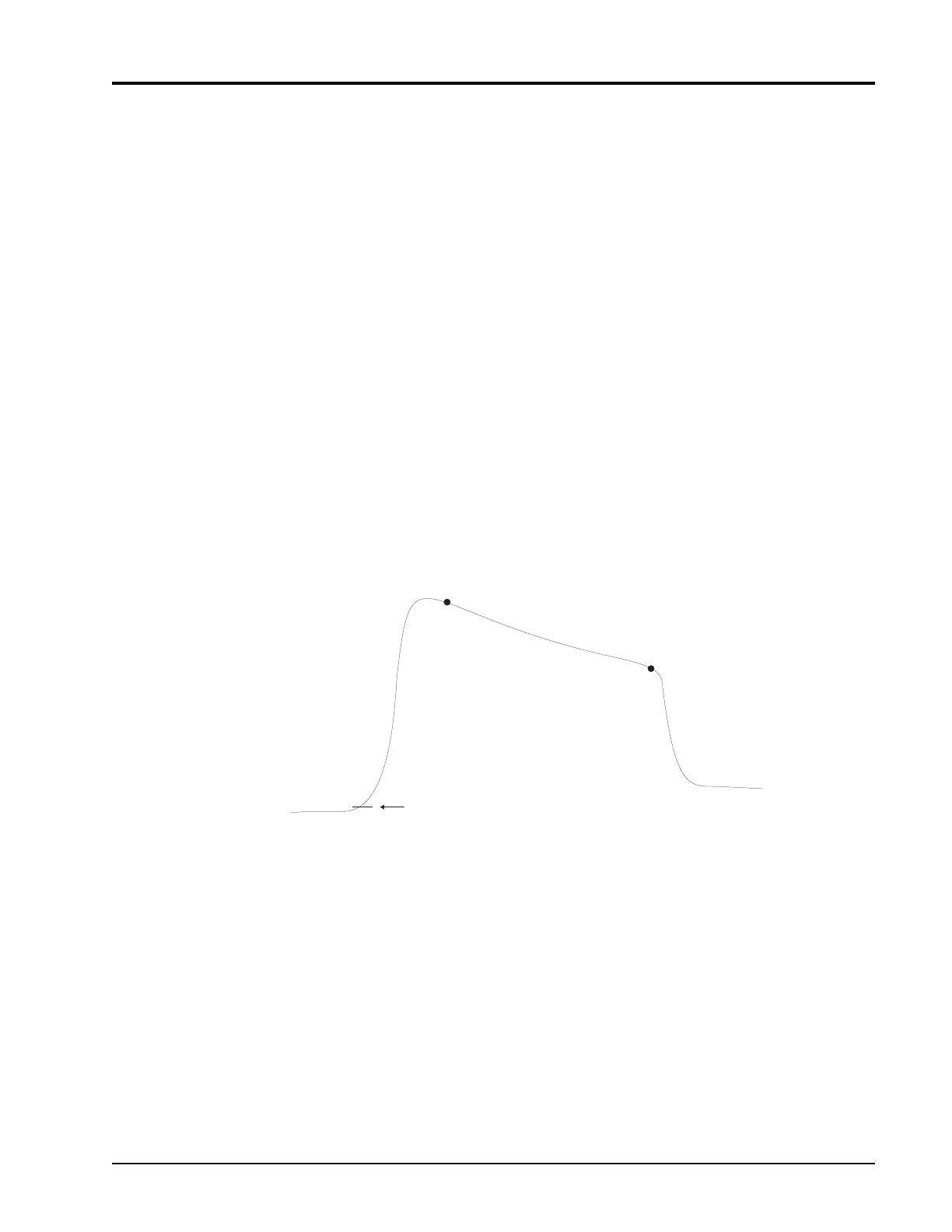
Figure 2-15: SD Setting for Measuring Pulse Droop
Detector Out
Trigger Level
t
1
t
2
 Loading...