Operation
Manual 21568, Rev. F, March 2008
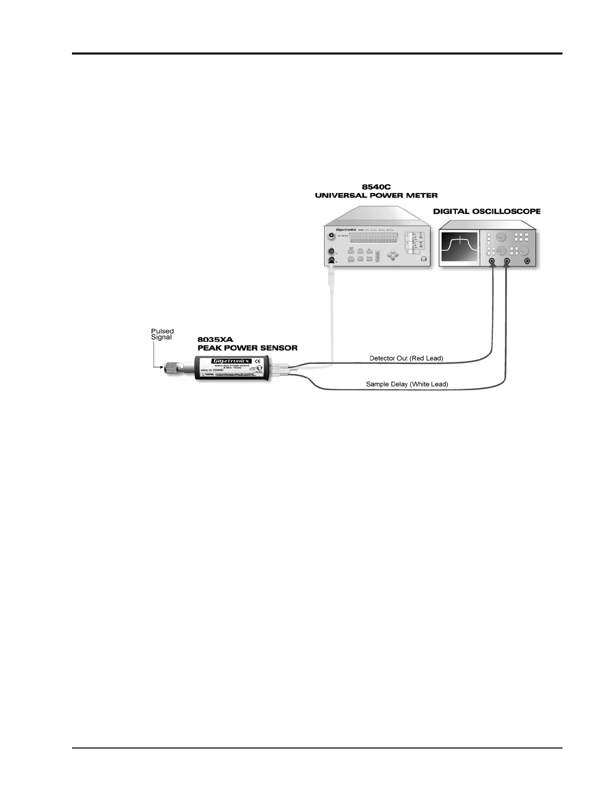
2.3.6 Real Time Pulse Profile and Sample Position Display
The Detector Out connector on the rear of the 8035XA Series Peak Power Sensor can be
connected to any common oscilloscope for a real-time amplitude profile of your signal, delayed
by about 120
ns.
Connect the SMB to BNC cables to your oscilloscope (digital scope preferred - especially for
sample delay setting >500 µs) as shown in Figure
2-12.
Figure 2-12: Pulse Profile and Sample Delay Test Setup
Use the Sample Delay output as an oscilloscope trigger source. This waveform rises at the
trigger point and falls at the sample point; thus, it provides both a stable scope trigger source
and a precise indicator of the trigger point and sample point.
The time length of the sample delay pulse is the sum of the sample delay which is displayed on
the Series 8540 power meter front panel, and the sample delay offset which is available
through the menu.
 Loading...