Series 8035XA Peak Power Sensors
2-6 Manual 21568, Rev. F, March 2008
2.3 Sample Delay
Sample Delay is the time value in nano-, micro-, or milliseconds that appears on the Series
8540 display after an 8035XA Series sensor has been calibrated. This is the length of time
between the trigger point and the sample point on the pulsed signal. This capability allows you
to measure the power level of your pulsed signal at any time point along its amplitude path. The
power level displayed is the true, sampled signal level at the time position that you specified;
the pulse level is not interpolated from two adjacent samples as is common in random sampling
oscilloscope-type peak power meters.
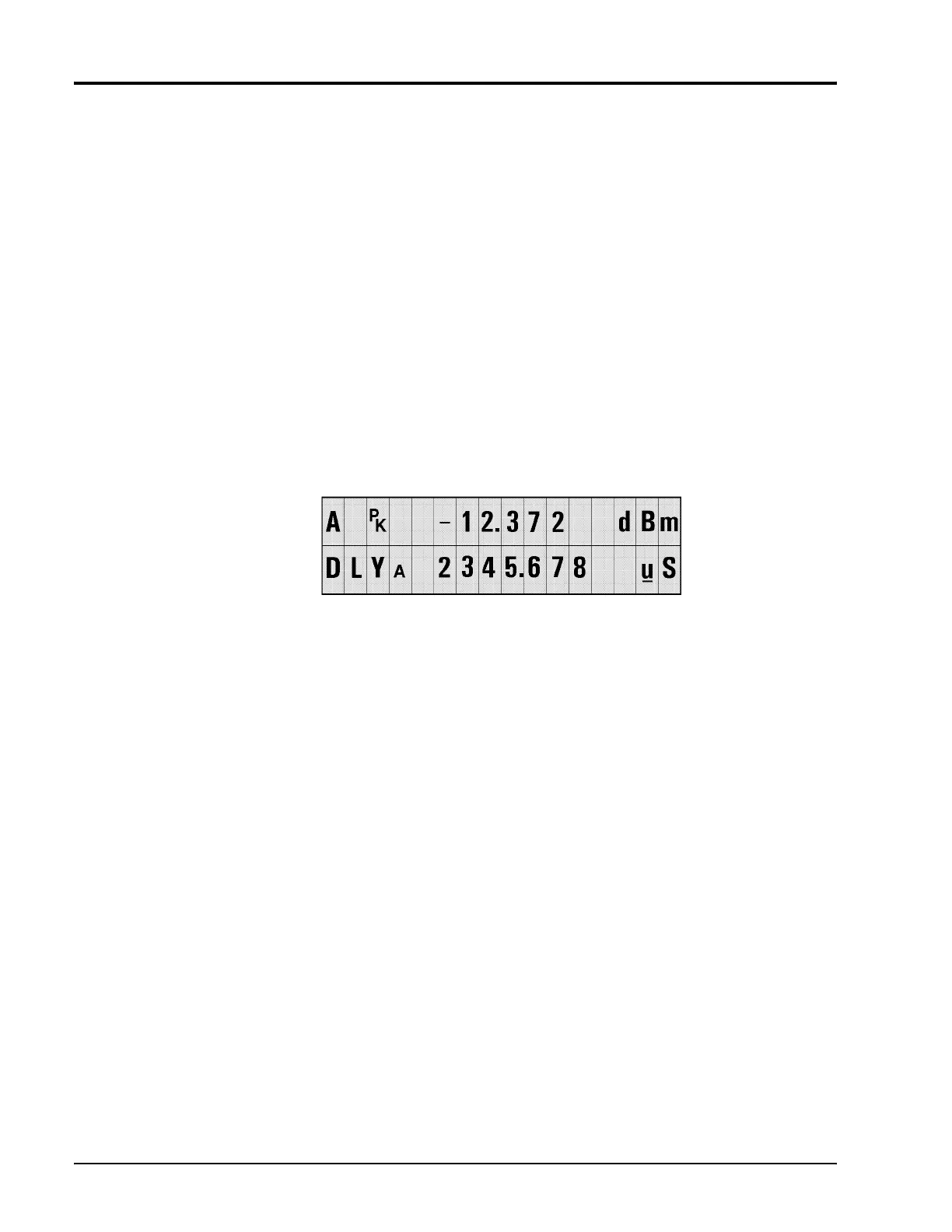
Sample delay is fully adjustable from -20 ns to 100 ms. On the 8541/2 front panel, use the
arrow keys to position the cursor and adjust the time values. Seven digits, four to the left of the
decimal and three to the right of the decimal, can be edited in the microsecond (ns) and
millisecond (ms) ranges (see Figure
2-4 for an example.) The nanosecond range
allows four digits to the left of the decimal, but only a .0 or .5 to the right of the decimal.
The 0.0 ns time delay setting will be close to the trigger level when internal triggering is used. If
your measurements require definition of the 0.0 ns position, use Sample Delay Offset to adjust
for small triggering variations.
Figure 2-4: Sample Delay Adjustment Display
Full 0.5 ns resolution is always possible regardless of the front panel units display. On the
millisecond ranges, small nanosecond level increments in sample delay can be performed by
incrementing Sample Dly Offset in the Peak Sensor Setup menu tree. In addition to allowing
control of small nanosecond range sample delay increments while currently displaying
millisecond ranges, sample delay offsets allow you to compensate for cabling and circuit time
delays in your test setup. The sensor delay is the sum of DLY
A
and DLY OFFSET
A
(or DLY
B
and DLY OFFSET
B
)
 Loading...