Zoning Diagram Hazardous Locations
MDE-5427E Latitude
™
Installation Manual · July 2022 Page 3-1
3 – Hazardous Locations
Zoning Diagram
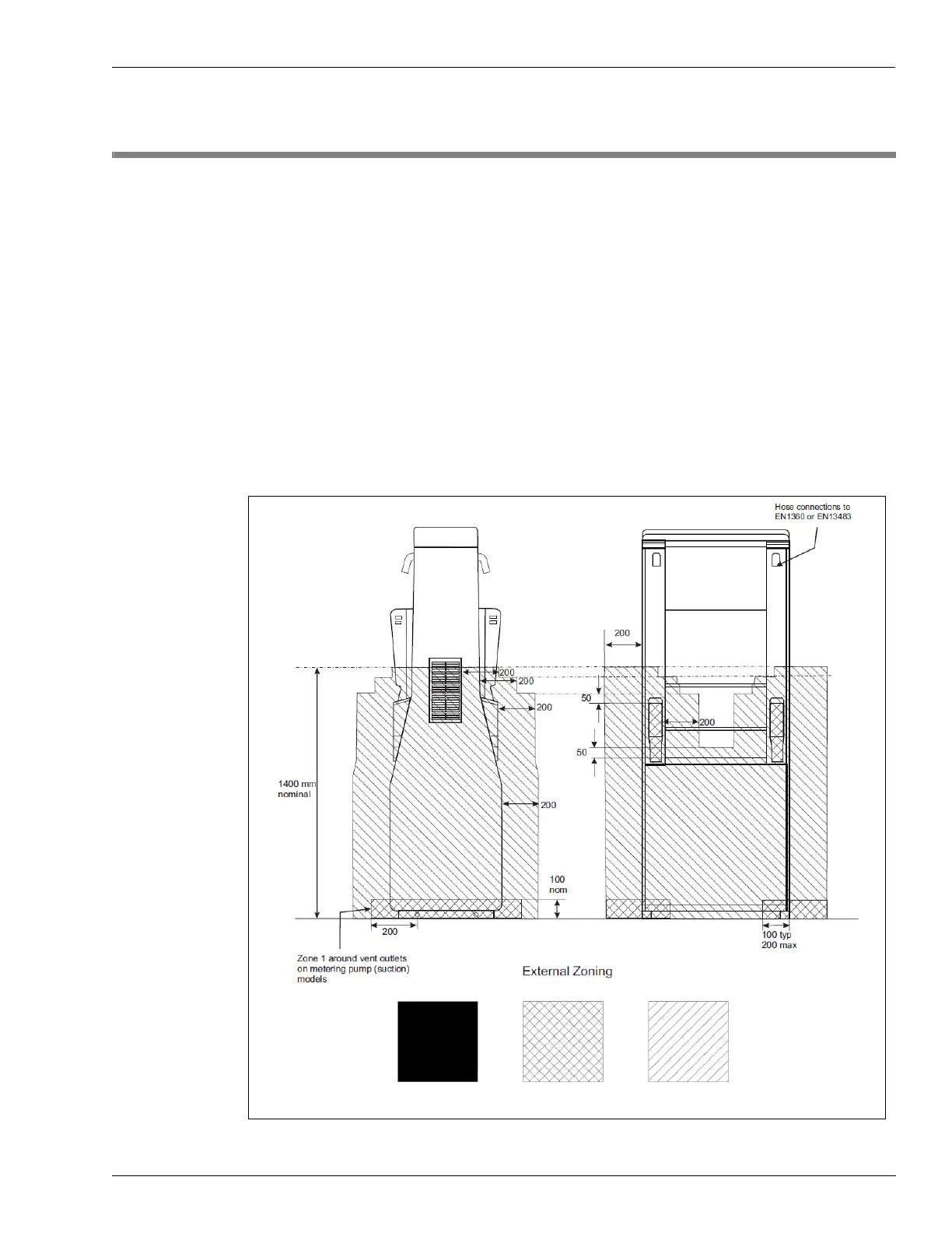
The dispenser must be installed to not compromise the zones illustrated in the following
Figure 3-1 and Figure 3-2 on page 3-2.
The zones 0, 1, and 2 indicated in th
e zoning diagrams define the probability of the hazard
actually being present in flammable concentrations.
• Zone 0:
A place in which an explosive atmosphere is present continuously or for long
periods or frequently.
• Zone 1:
A place in which an explosive atmosphere is likely to occur in normal operation
occasionally.
• Zone 2:
A place in which an explosive atmosphere mist is not likely to occur in normal
operation but, if it does occur, will persist for a short period only.
Figure 3-1: Zoning Diagram for LS-200 Lane Configuration
 Loading...