Connecting Pump/Dispenser Inlet Pipes Installing Units on Island
Page 5-16 MDE-5427E Latitude
™
Installation Manual · July 2022
For Latitude installations:
• Selection of proper components mounted to the bottom of the strainer housing is critical in
maintaining the proper location of the shear valve groove of the shear valve to the base
plane of the dispenser. You must follow the shear valve manufacturer’s required
positioning for this groove.
• A check valve is strongly recommen
ded. When installed, Gilbarco recommends using
N23274, which is approximately 2-1/2-inch long and can take the place of the close nipple
located above the union. Failure to install a check valve here can result in fuel sale
indication when the fueling position is activated with the nozzle closed and the check
valve back at the STP is leaking.
• A union is required above the shear valve.
• A Morrison male end Shear Valve [N23047 (Morrison # 636M-0200AV)]
can be used to
properly maintain the position of the shear groove. The installer must verify if other
manufacturer’s shear valves will ensure proper positioning of the shear groove as per their
specifications.
• Not all double poppet shear valve models or styles will fi
t the Latitude unit.
• Other combinations of unions, chec
k valves, and shear valves may be possible and still
maintain proper location of the shear groove.
• Removal of a strainer from the system will void warranty
.
Follow the shear valve manufacturer
’s instructions for installation procedures, testing, and so
on.
• Install the shear valve on each
product inlet pipe.
Note: Latitude dispensers require 1-1/2-inch male
top shear valves. Gilbarco strongly
recommends using double poppet shear valves that shut off flow from both storage
tanks and internal to the unit (for example, OPW #10BHMP or
Exxon
®
- OPW # 10RMSP). The Latitude dispensers use 2-inches male top shear
valves (for example, Morrison Bros. 2” 636 m).
• For Latitude units, install the shear valve
on each 2-inch inlet and outlet.
• Install a shear valve on the master dispenser satellite outlet and at sat
ellite inlet.
• Do not mount the shear valve upside down.
• Ensure that the valve linkage is ac
cessible and has no interference to open or close from
other piping, structure, or components.
Note: The dispenser product inlet pipes must be
aligned with the shear valve. Do not
restrict shear valve linkage with pipes, braces, and so on.
• Test shear valve operation.
• Close the shear valve until equipme
nt start-up. Cap the inlet pipe. This prevents dirt and
other particles from entering the product line. It also prevents fuel spillage.
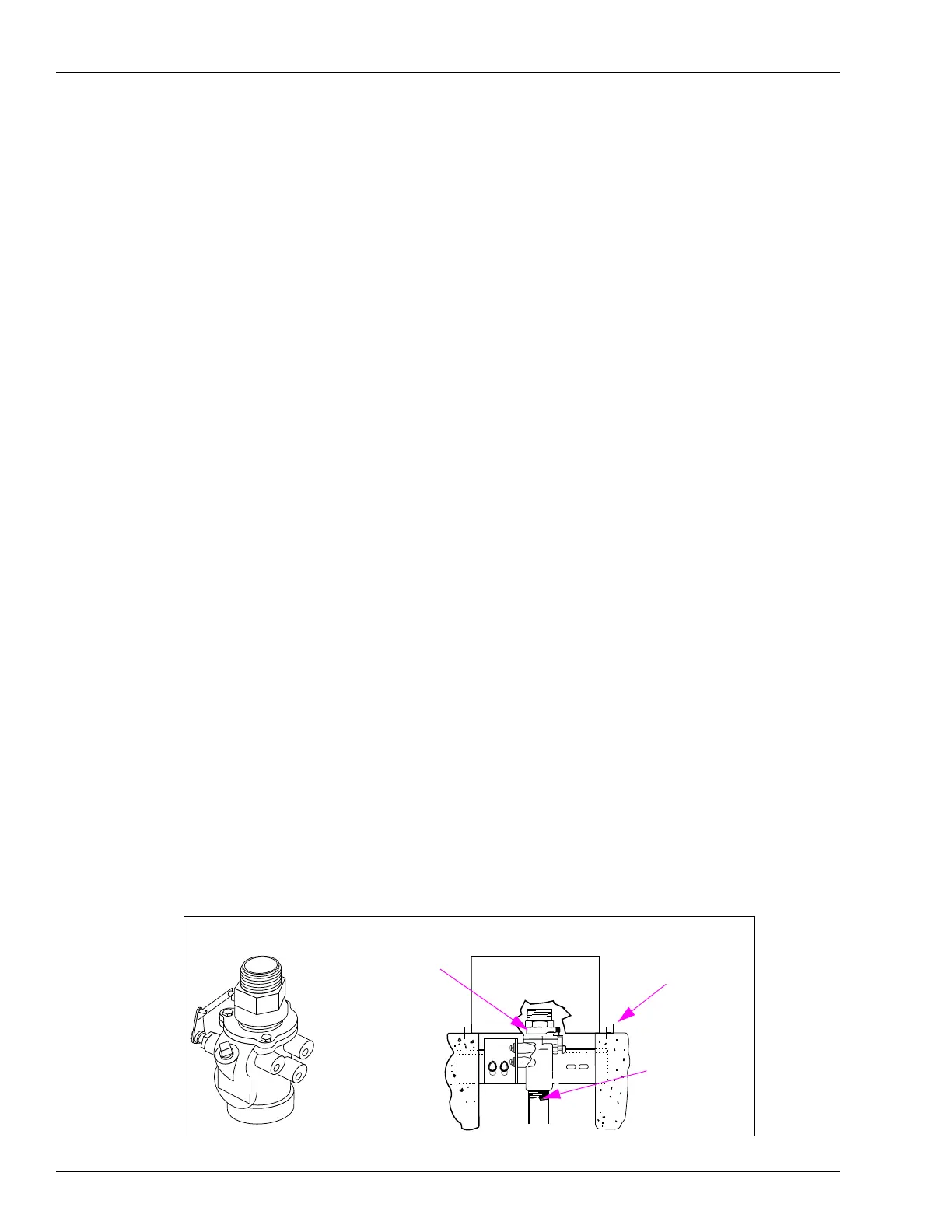
Figure 5-11: Shear Valve
Shear Valve
Shear valve groove location must be
flush to island surface ± 0.75’
Shear Groove
Island Surface
Product Inlet Pipe
 Loading...