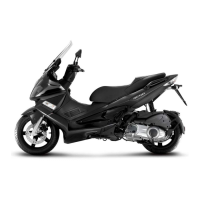
Turn signals system check
The turn indicator circuit is managed by an inter-
mittent device. If there are any problems with this
circuit check:
- The 7,5A fuse indicated in the photograph after
removing the front cowling.
- Using a multimeter, that the BLACK-BLUE cable
to the turn indicator connector has a voltage of
+12V
- To check the efficiency of the bulbs, apply a ten-
sion of +12V to the WHITE-BLUE cable of the
indicator switch for the right bulbs and to the PINK
cable for the left bulbs.
See also
Legshield
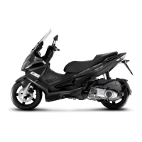
level indicators
Composed of fuel level transmitter, analogical
reading instrument and fuel reserve light.
If problems occur check:
- The fuel reserve light
- The 7,5A fuse in the photograph after having re-
moved the front casing
The WHITE cable of the instrument group has a voltage of +12V
Using the current meter, the ohmic values of the fuel level transmitter moving the arm with the floater.
Limit values:
position of empty tank = 87 ÷ 97 Ω
position of ½ empty tank = 34 ÷ 42 Ω
position of full tank < 7 Ω
See also
Legshield
Electrical system Runner Purejet
ELE SYS - 12