13
Girard Systems © 2005
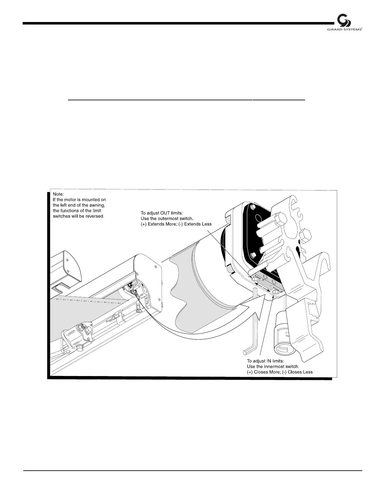
2. Adjust the limit switches with the black plastic key (provided) or a 4mm Allen wrench.
3. Extend the awning a few feet and locate the cylindrical awning motor mounted inside the
awning roller tube (standard installation is at the right/front end of the awning). The limit
switches are mounted on the aluminum (silver) casing at the exposed end of the motor. At
the limit switches are two black directional arrows, each with a plus (+) and a minus (-) sign.
The actual limit switch is the recessed hole next to the corresponding arrow.
4. Adjust limits according to the directional arrows (see Fig. 5 callout). A 1/4 turn represents
approximately 1" of awning movement. Never set outward limits so that fabric is slack after
full arm extension. Adjust limit switches until the motor stops at the exact time that the
arms lock into position.
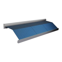
The diagram below refers only to motors with aluminum (silver) casings.
Figure 5
adjusting Motor limit switches