42
Girard Systems © 2005
3. Drill one 3/8" hole for anemometer wire.
4. Pull anemometer cord back through original packaging hole until cord dangles straight down
from exit point of anemometer body (see Fig. 26).
5. Seal original packaging hole with silicone.
6. Feed anemometer cord (containing blue and brown wires) through hole in roof, leaving three
to four inches (3–4") of slack, and secure anemometer with sheet metal screws.
7. Seal top footprint of anemometer after securing it to roof.
N. CONTROL BOX and ACL CURRENT-LIMITING DEVICE
(Partial Hardware Installation Only)
1. Determine mounting location for hardware referenced above. The back wall of a cabinet is
ideal, as both awning motor and anemometer cords will generally enter a cabinet from
outside and the back wall provides a solid mounting surface.
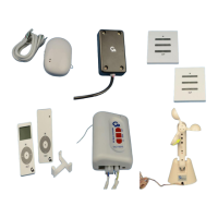
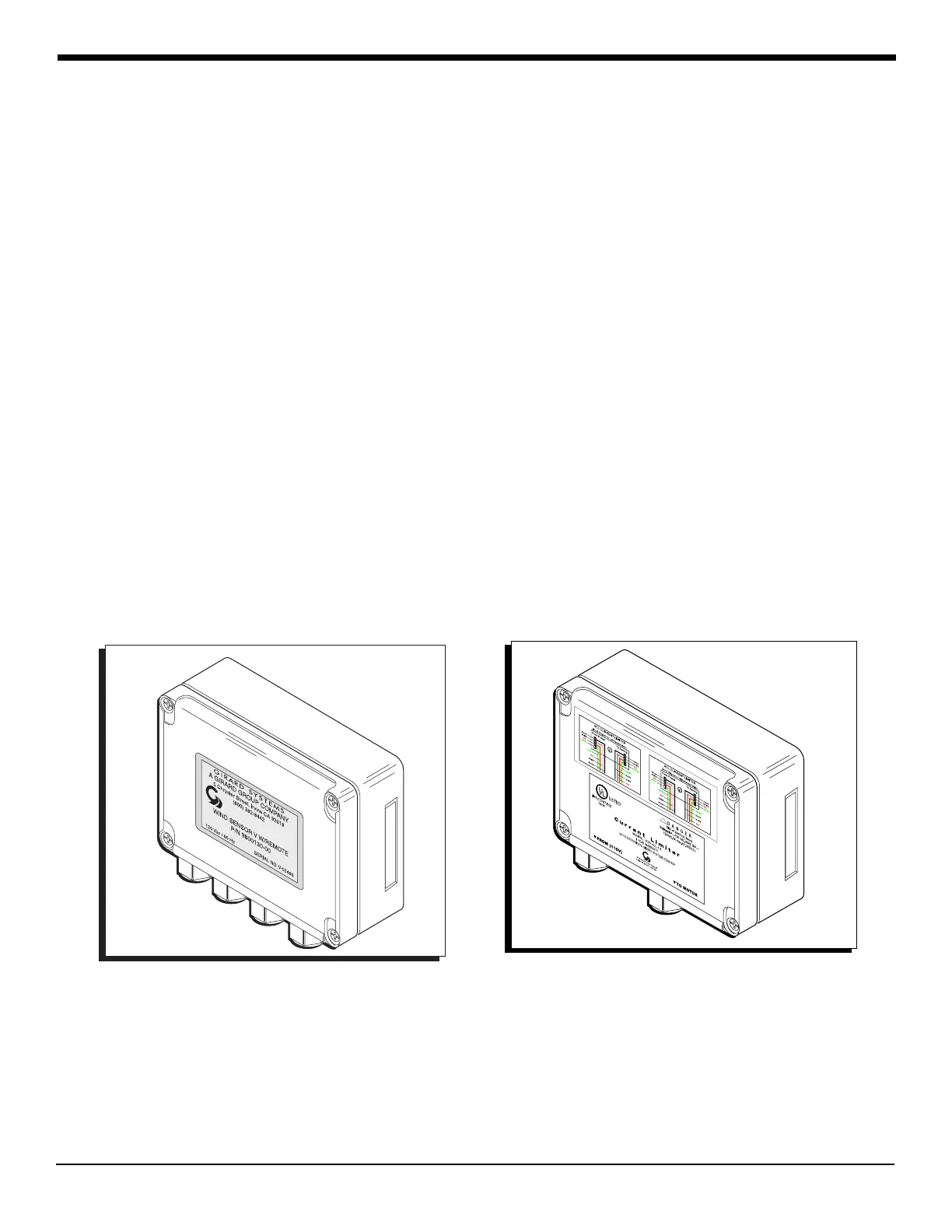
2. Use screwdriver to remove faceplates of both control box and ACL current-limiting device
(Figs. 27 and 28).
Figure 27 control box Figure 28 ACL current-limiting device
3. Mount the control box using wood screws.
4. Remove two (2) rubberized knockouts on each side of ACL housing.
 Loading...