46
Girard Systems © 2005
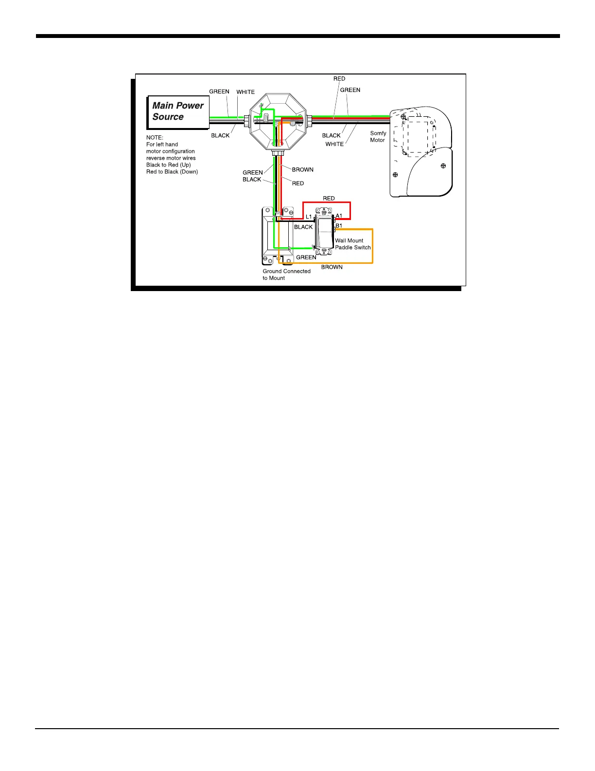
Figure 31 g-1500 door awning wiring diagram
P. g-2000 WALL MOUNT (rOCKER) SWITCH
(Electrical Installation)
1. Run wall mount switch cable wiring from switch box to control box:
a. Insert black and red wires through wiring guide holes at bottom of control box.
b. Connect wires to first and third terminals (counting from bottom to top) in control
box, located just to the right of “Low Voltage Switch” label (see bottom center portion
of Wiring Diagram, Fig. 30).
P. REMOTE SWITCH
(Hardware Installation)
1. Determine mounting location out of reach of small children or accidental contact. Be sure
there is no wiring behind mounting screws.
a. Place remote control mounting bracket/cradle into position and mount
using screws and anchors provided (Fig. 34).
P. Remote motor
(Electrical Installation)