47
Girard Systems © 2005
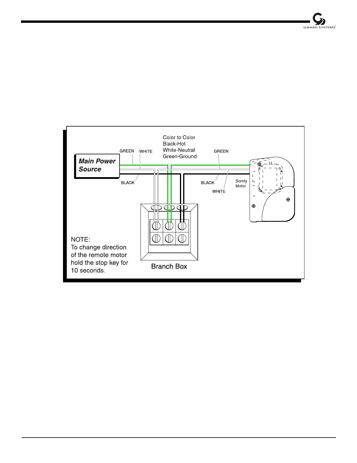
1. Insert all the wires through wiring guide holes at the bottom of branch box.
2. Connect wires as follows:
a. Black wire (L1): from motor to black wire form main power source.
b. White wire: from motor to white wire from main power source.
c. Green ground wires (3): connect wiresfrom branch box, motor and main power source to
each other, ground to branch box and then secure all connections.
(see bottom center portion of Wiring Diagram, Fig. 32).
Figure 32 Remote motor wiring diagram
Hz Operator wiring
NOTE: All electrical work must comply to all Rvia codes and national electrical codes.
1. It is recommended that provisions be made to cut power individually when wiring Hz
operators.
((
((
(
This cThis c
This cThis c
This c
an be in the foran be in the for
an be in the foran be in the for
an be in the for
m ofm of
m ofm of
m of
an in-line OFF/ON switc an in-line OFF/ON switc
an in-line OFF/ON switc an in-line OFF/ON switc
an in-line OFF/ON switc
h.h.
h.h.
h.
The abilitThe abilit
The abilitThe abilit
The abilit
y to cut the powy to cut the pow
y to cut the powy to cut the pow
y to cut the pow
ee
ee
e
r to ear to ea
r to ear to ea
r to ea
cc
cc
c
h motorh motor
h motorh motor
h motor
indiindi
indiindi
indi
vidually is rvidually is r
vidually is rvidually is r
vidually is r
equirequir
equirequir
equir
ed to easily pred to easily pr
ed to easily pred to easily pr
ed to easily pr
ogog
ogog
og
rr
rr
r
am the motor).am the motor).
am the motor).am the motor).
am the motor).
NOTE: Wiring Diagram of the G-2000 is referred to throughout
balance of Installation Manual.