29
Girard Systems © 2005
8) If the arm you are replacing has a fixed bolt insert the arm into the shoulder ensuring that the
fixed bolt on the arm goes through the pitch adjustment assembly, through the square tube, and
though the washer, which are components inside the shoulder. Insert the front, loose bolt and
nut.
If the arm you are replacing does not have a fixed bolt use the bolt supplied with the arm to
slide through the square tube for the shoulder support then through the pitch adjust assembly
and into the arm connection plate. Insert the front, loose bolt and nut.
9) Proceed with un-banding arm very carefully as this arm is under heavy tension than fasten to
lead rail refer to #8 procedure.
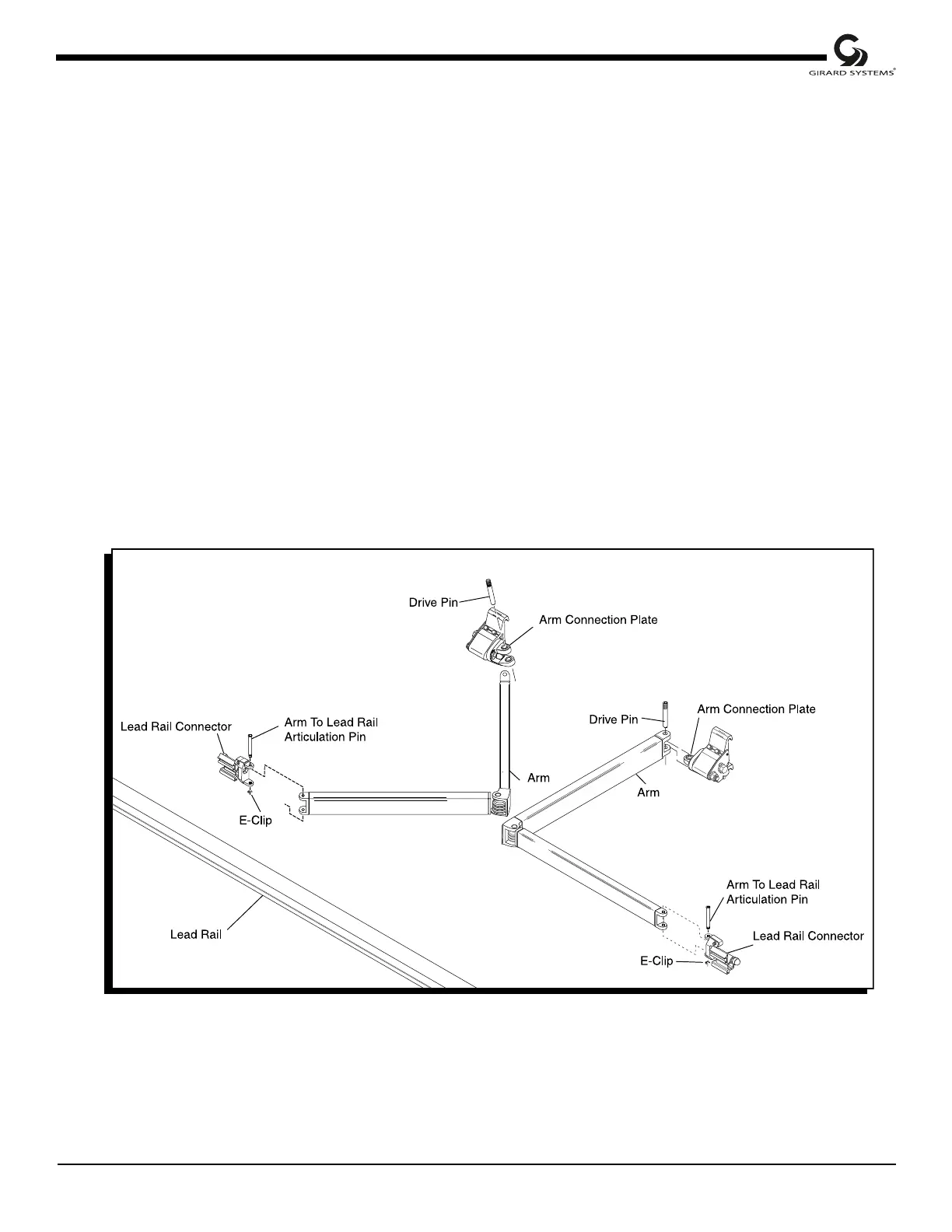
10) Attach the front of the arm to its connection point at the lead rail by replacing the pivot pin from
the top, and securing it with the retaining ring of exploded view). Then slide into the lead rail
connection and replace the nut and washer. Tighten both lock nuts, one turn from being tight, at
the upper end of the arm. Adjust the pitch angle of the arm to match the other arms by rotating
the head of the pitch adjustment screw. Rotate this screw in a clockwise direction (looking form
the bottom up) to lower the arm. Likewise, rotating this screw in a counter clockwise direction
will raise the arm. Tighten both lock nuts. See also; adjusting the Pitch Angle, in the
‘Adjustment’ section of this manual (Figure 16).
Figure 16
Parts BreakDown of Lateral Arm
 Loading...