www.gisma-connectors.de20Cabling Instructions series 10+22 Revision F - 11/2018
CABLING INSTRUCTIONS - SERIES 10 + 22
Step 3:
Danach das Formteil auf das äussere Endgehäuse schieben,
die untere Schelle montieren (siehe Seite 21 ff.) und mit PUR-
Vergussmasse füllen.
ACHTUNG:
Bei erhöhten Anforderungen an die elektromagnetische
Verträglichkeit ist ein zusätzlicher Vergussschritt
notwendig (siehe Punkt 3a). Für besondere Kabel und
Anwendungen sind spezielle Endgehäuseadapter
verfügbar.
With increased requirements for electromagnetic
compatibility an additional moulding step is necessary
(see step 3a). In case of special cables and applications
GISMA offers individual endbell adapters.
Das Vergiessen des Endgehäuses erfolgt in zwei Schritten.
Schritt 3a:
Bei erhöhten Anforderungen an die elektromagnetische
Verträglichkeit empfehlen wir die Verwendung von EMV-
Klebeband. Die Langlöcher im Bereich X werden dazu
abgeklebt. Dabei wird ein Langloch zum Vergiessen
ausgespart.
Der anschliessende Verguss muss in waagerechter
Position erfolgen, um den Endgehäuseadapter optimal zu
füllen. Nach Beenden des Vergussschrittes wird das
ausgesparte Langloch ebenfalls mit EMV-Klebeband
versiegelt.
Alle Vergussendgehäuseadapter müssen grundsätzlich im
ersten Arbeitsschritt bis zu den Einfräsungen, d.h. im An-
schlussbereich, mit Schottvergussmasse gefüllt werden. Wir
empfehlen, den Endgehäuseadapter komplett mit Schott-
vergussmasse auszugiessen (siehe Seite 9 Pos. 6).
ACHTUNG:
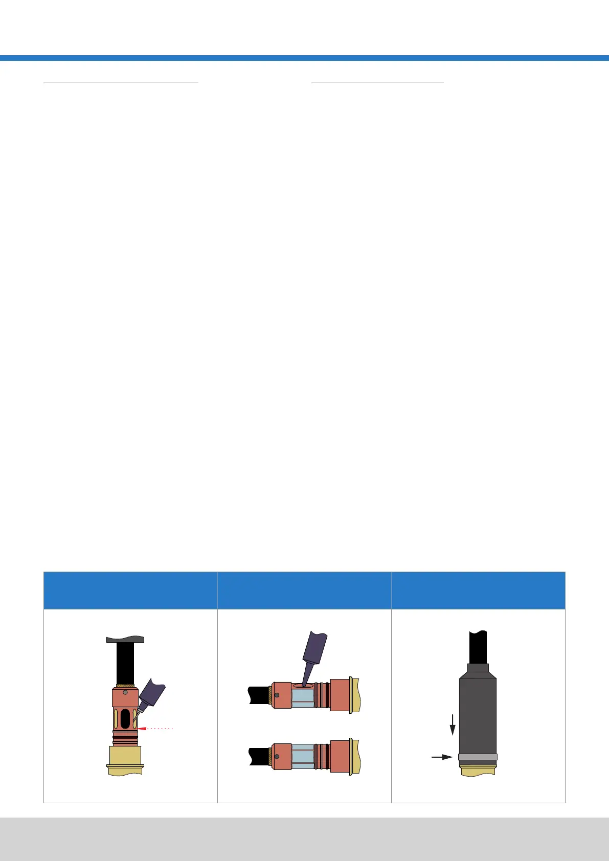
Zunächst muss der Endgehäuseadapter mit Schottverguss-
masse gefüllt werden (dafür wird die Spritze in die Einfräsung
des Endgehäuseadapters gehalten).
Schritt 3b:
Schritt 3:
Danach wird das Formteil auf das Endgehäuse geschoben
und die untere Schelle montiert (siehe dazu Seite 21 ff.).
VERGIESSEN DES ENDGEHÄUSES MOULDING OF THE ENDBELL
Moulding of the endbell should be carried out in 2 phases.
ATTENTION:
First the endbell adapter must be filled with hard moulding
compound (here the syringe is to remain in one of the grooves
of the endbell adapter).
Afterwards, push the boot onto the outer endbell, attach the
bottom clamp (see page 21 ff.) and fill up with PUR-moulding
compound.
Step 3a:
With increased requirements for electromagnetic compatibility
we recommend using EMV-tape (EMV-KLEBEBAND). The
slotted holes in the area X must be taped save for one hole
that is used for the filling process.
ATTENTION:
Afterwards, push the boot onto the outer endbell and attach
the bottom clamp (see page 21 ff.).
All moulding endbells must first be filled up to the grooves with
hard moulding compound. We recommend filling the endbell
adapter completely with hard moulding compound (see page
9 item 6).
The moulding process has to be carried out in horizontal
position to achieve an optimal filling result. After
completion of the second moulding, the omitted filling
hole has to be sealed with EMV-tape as well.
Step 3b:
 Loading...